EXPERT INSIGHT
What’s (Arguably) the AM Industry’s Biggest Blind Spot? Looking at Toolpath Optimization in Isolation
Metal laser powder bed fusion’s (LPBF) maturity means innovation is no longer limited by machine hardware. This reality — combined with a broader array of materials and a greater understanding of additive manufacturing’s (AM) design freedom — has led to seemingly impossible geometries and exciting new applications. However, the question remains: why is it so hard to move from thrilling breakthroughs to consistent series production?
Forward-thinking leadership teams looking to bring new metal AM applications from concept to series production aren’t thinking about just printing: that step is relatively straightforward. They’re more concerned about industrializing the process, repeatedly, cost-effectively, and compliantly, without increasing operational friction. That’s why toolpath optimization is a critical enabler and a powerful lever, as you can improve part performance and reduce costs. But it’s only one part of a much larger equation.
Toolpath optimization is a catalyst for faster NPI
What does it truly take to scale metal LPBF?
New product introduction (NPI) in metal LPBF is complex and can either make or break your production schedule. Every new application introduces unknown variables: material behavior, process parameters, thermal management, surface requirements, cost structures — and the list goes on with each iteration.
Additionally, every decision has a massive effect on future outcomes, especially when ramping up production. Toolpath optimization is a great way to meet internal cost and mechanical property targets, helping R&D teams move from budding ideas to production readiness.
Optimizing toolpaths with the right software allows you to:
- Enhance part quality and first-time-right manufacturing
- Improve build speed for cost control
- Print parts with more intricate geometries
- Reduce post-processing costs via support structure optimization
- Expand material options by improving material properties
This is where application-specific toolpath engineering — enabled by CO-AM Brix’s toolpath visualization, automation of design experiments, and parameter tweaking — can significantly streamline your NPI process.
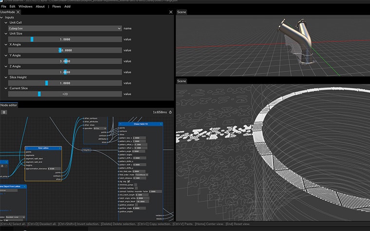
Instead of relying on generic parameters or machine-locked toolpath strategies, engineers can rapidly iterate and actively manage factors such as energy, heat, and materials interaction. And the best bit is that all of this can be achieved right from the start, rather than later in this process.
Let’s explore how toolpath engineering moves the needle during NPI.
1. Enhancing part quality to achieve first-time-right manufacturing
Quality issues discovered late in the production process are some of the most expensive failures in metal AM. Toolpath scan strategies benefit part quality by improving surface finishing and increasing part density, while minimizing issues such as:
- Managing residual stress
- Reducing microstructural defects
- Avoiding gas entrapment
- Load balancing
Preventing these quality issues increases first-time-right manufacturing rates, leading to lower scrap, fewer reprints, faster decision-making, and greater confidence among engineers, as they know how to address these challenges when moving to series production.
2. Improving build speed for cost control
Toolpath optimization is not just about printing better; it’s about printing faster, more efficiently, and in a controlled way. Intelligent scan strategies and parameter optimization — like hull and core and jump optimization — can significantly reduce build times while maintaining mechanical performance and surface quality.
The result? Higher machine utilization, shorter build times, and faster time-to-market — KPIs that directly impact your business case for scaling LPBF. And for leaders looking to maximize throughput and cost, improving build speed is one of the quickest ways to manage the economic impact of LPBF production, from pilot builds to sizable volumes.
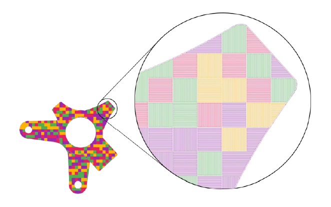
3. Printing parts with more intricate geometries
Complex internal channels. Thin walls. Lattice-based structures. All of these features are core components for the rise of large, complex metal 3D-printed parts (through implicit model integration with nTop’s workflows) and high-performance LPBF applications. However, they (usually) fail not because of design faults, but because of insufficient toolpath control due to over- or underheating. These lead to issues such as porosity, surface finishing, reduced strength, and residual stress.
Advanced toolpath engineering enables localized control and regulated heat distribution during layer deposition. Engineers can reliably create intricate geometries, even as designs evolve during NPI. This makes AM’s design freedom a repeatable, manufacturable process for certifiable parts — and not a one-off occurrence.
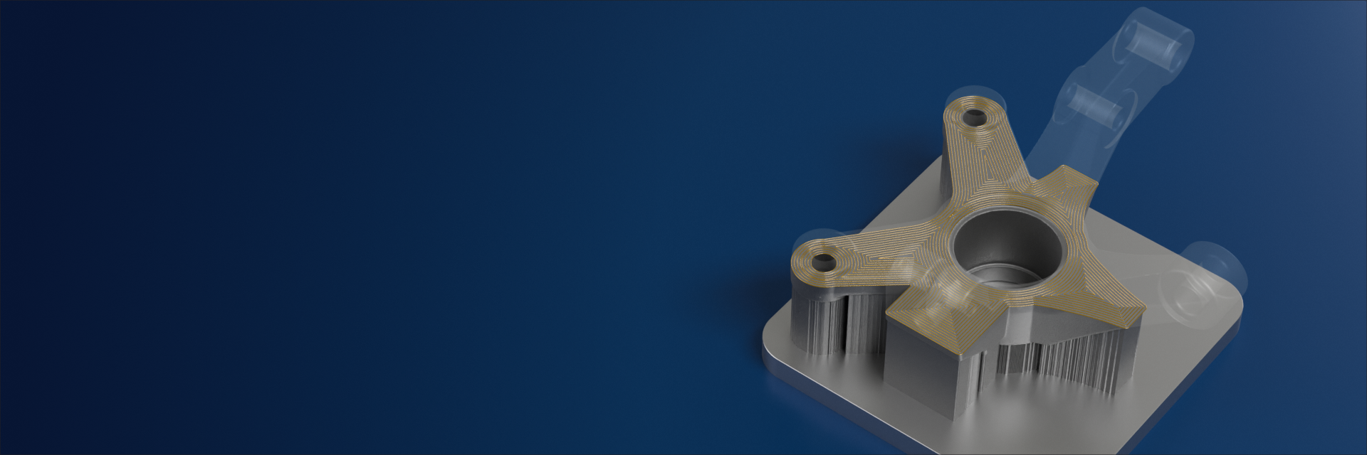
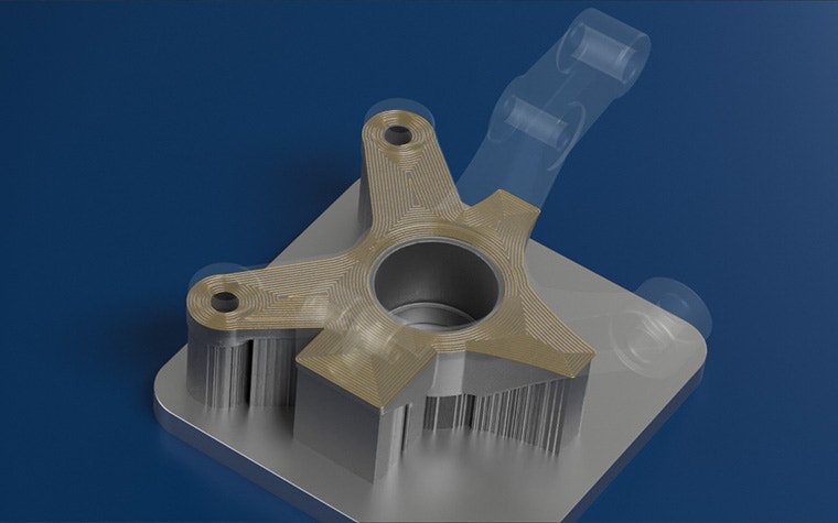
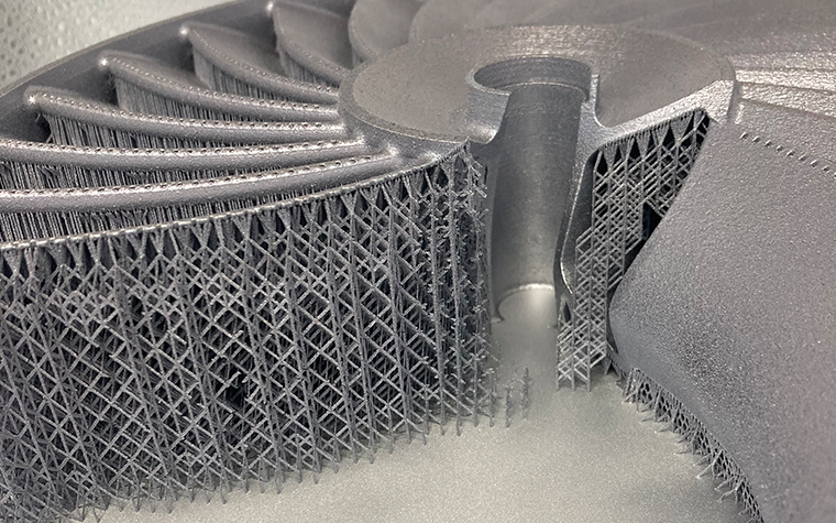
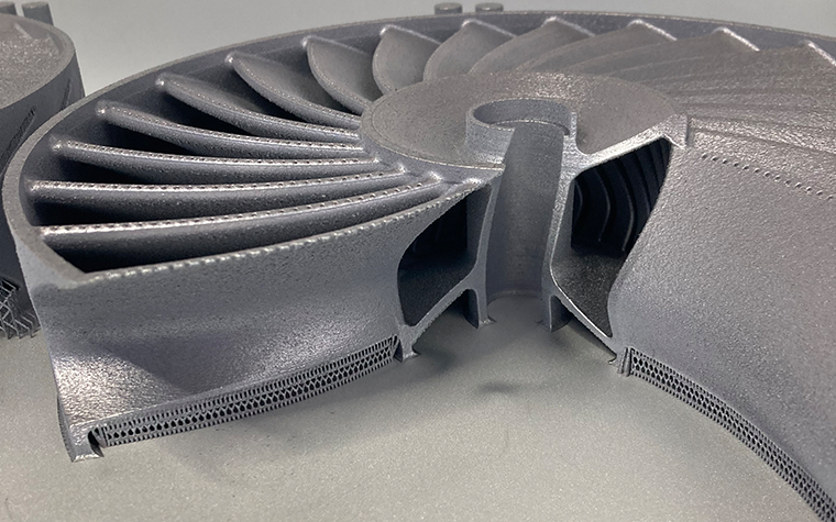
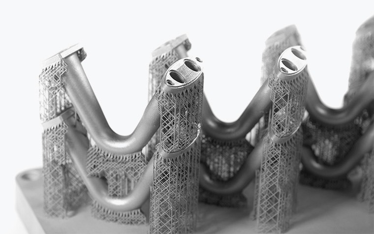
4. Reducing post-processing costs via support structure optimization
Supports are often treated as a necessary evil in LPBF, but with the right toolpath strategies, you can significantly reduce or eliminate them through intelligently redesigned support structures. How? Support-aware toolpaths (such as low-angle printing), lower material consumption, reduce heat accumulation, and simplify support removal.
Support-free printing of low-angled surfaces and internal features minimize expensive post-processing steps without compromising surface quality: a win-win for your production.
The result is not just better prints, lower post-processing times, and fewer support strategy iterations but greater design freedom and a broader range of AM applications. These factors are critical when scaling beyond low-volume production.
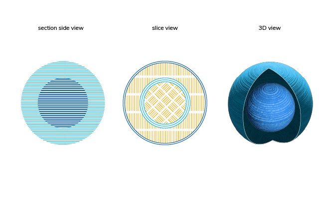
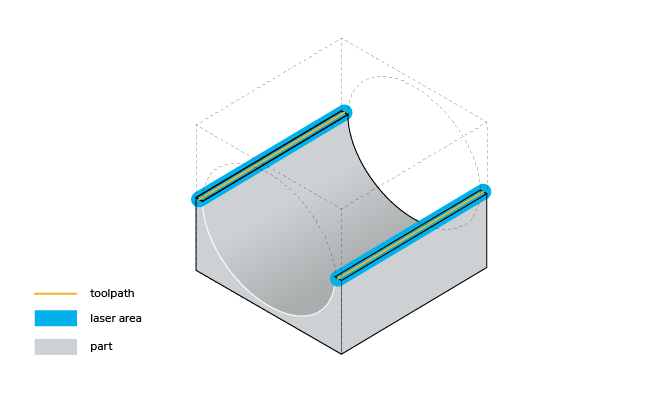
This 3D-printed impeller model showcases advanced process control, including support-free printing of low-angled surfaces and internal channels. The end result unlocks new AM applications while drastically minimizing the amount of support in a build by assigning different scanning parameters to down-skin zones based on the overhang angle, enabling support-free printing.
5. Expanding material options by improving material properties
Many organizations stick to tried-and-tested materials because qualifying alternatives seems too laborious and time-consuming. Toolpath optimization addresses these concerns head-on. In fact, specific toolpath strategies have enabled materials to perform beyond their standard datasheet properties.
By adapting scan strategies to control aspects such as melt pool behavior, thermal gradients, and energy input, teams can achieve noticeable improvements regarding density, fatigue performance, and consistency. As a result, overlooked and seemingly risky materials can become viable options, opening up new applications and potential cost savings.
For example, Materialise collaborated with KU Leuven to test local microstructure engineering of super duplex stainless steel using two LPBF laser beams in parallel. With an additional beam trailing the primary melting laser, the team managed to extend the melt pool and control the print's microstructural phase at different locations on the same build platform.
The input files generated by our Build Processor Software Development Kit (BP SDK), combined with accurate calibration from Materalise Control Platform (MCP), enabled in-situ heat treatment and local microstructure control, as the synced dual-laser settings operated within 10-20 microseconds of each other.
Such discoveries directly impact NPI, reducing the number of qualification loops while expanding your material portfolio. A broader range of materials benefits companies in industries like aerospace, defense, energy, and medical device, laying the groundwork for future innovations rather than risking delays by focusing on selecting the right material.
Toolpath optimization alone isn’t enough
Scaling LPBF requires a repeatable recipe and control across the entire digital thread
Toolpath engineering is essential, but shouldn’t be used in isolation. Instead of perfecting this single step, you need to include it alongside your own production recipe to ensure repeatable results. This is where a software ecosystem approach becomes critical, ensuring that your hard work achieved during NPI is maintained and magnified for series production.
We recommend using a three-step process:
- Develop your model (aka, your recipe) by choosing the right software ingredients
- Execute the model and validate standardized workflows to ensure repeatability and compliance
- Scale and integrate a data backbone to automate production and ensure end-to-end traceability
Successful industrialization requires a connected workflow operating in tandem. It’s the most logical way to ensure cost efficiency and make AM part production more economical.
First, develop your model by optimizing toolpaths in conjunction with orientation and support generation based on the production criteria (e.g., thin walls). Combining all the factors that impact job file creation in a single environment enables you to achieve repeatable quality. Solutions like CO-AM Brix, Magics, e-Stage for Metal+, and Ansys Simulation work cohesively to optimize and manufacture first-time-right parts while controlling costs.
Next, leverage quality processes to identify anomalies and visualize potential problem areas before printing, for example, with tools like Quality & Process Control (QPC). Its AI-powered layer analysis optimizes your parameters, which feed into developing your QC pass/fail strategies during production. Visibility and early detection of anomalies are key to mitigating costly failures.
After that, execute and validate standardized workflows. Implementing your model into production workflows is a surefire way to maintain repeatability, which is needed for compliance, particularly for regulated industries and organizations aiming to transition from concept to true serial production. CO-AM Brix’s automation and QPC’s pass/fail process are two prime examples of capturing AM know-how and streamlining tasks across operators.
Finally, successfully scale and integrate a connected data backbone for a repeatable and auditable process for compliance. Connected ecosystems like Materialise CO-AM combine build prep, toolpath engineering, production planning, in-situ process monitoring data, and quality insights into a single digital thread.
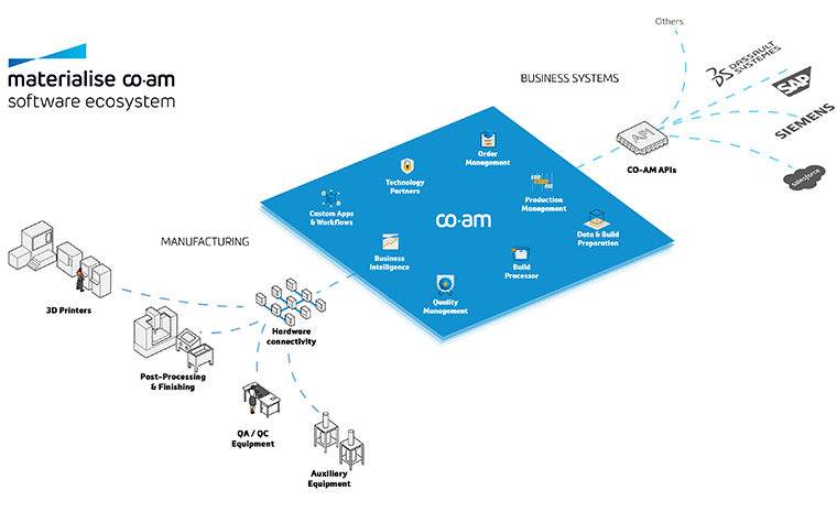
CO-AM not only improves operational efficiency but also enables traceability, compliance, and continuous improvement — all must-haves to scale industrial AM. Your future success will depend on software ecosystems that learn, adapt, and industrialize AM faster than your competitors do, rather than on isolated tools and programs.
Failure in metal LPBF isn’t down to the technology’s capabilities. More so, it’s because organizations don't build in processes and ecosystems that help scale from the start. However, the organizations that will succeed are those that align toolpaths, build preparation, quality control, and data continuity into a holistic production system — and not solely focus on toolpath optimization.
Because your machine’s laser shapes only the part, your software ecosystem determines whether it becomes a real product or application.
Share on:
You might also like
Never miss a story like this. Get curated content delivered straight to your inbox.