CUSTOMER STORY
Improving Metal AM Quality Using Computed Tomography
Tom Craeghs, Research Project Manager at Materialise, explains how Materialise and Volume Graphics are working together to ensure quality production of 3D-printed metal parts by applying computed tomography to additive manufacturing.
Quality is the buzzword of the moment in additive manufacturing and companies are investing heavily in digital solutions to improve it. I have seen a lot of advances in the past few years, both technological as well as economical, but any engineer involved in metal 3D printing in a professional capacity knows that we still have some ways to go before we can certify the quality of complex parts.
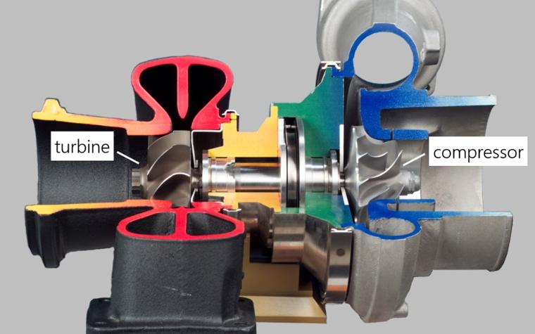
In this blog post, I want to share with you a recent case that we at Materialise have been exploring and that concerns the 3D printing of an impeller for turbocharged machines. Turbochargers are commonly used for increasing the efficiency and power output of internal combustion engines (ICEs), such as in cars. A turbocharger typically contains two impellers mounted on a common shaft: one of the impellers is used as a turbine, while the other impeller is used as a compressor.
Finding the right process parameters for metal parts
During operation, impellers rotate at high speeds and are exposed to high temperatures; fatigue is a real concern. The additively manufactured design is lighter than its casted counterpart, potentially enabling higher rotational speeds and improved performance. Minimizing porosity and achieving precise manufacturing with tight geometrical tolerances are crucial to ensure long-term operation of the manufactured parts.
When 3D printing an impeller, we have two clear goals in mind:
- The first goal is to minimize thermal distortions due to the printing process and to ensure symmetry of the part. An asymmetrical impeller can result in reduced efficiency at best and catastrophic damage at worst.
- The second goal is to keep porosity low; we aimed for a density above 99.9% for the impeller. This is especially important for lighter designs, in which porosity has a higher impact on fatigue life.
To achieve these quality goals in the 3D printing of impellers, we joined forces with Volume Graphics, a company providing software for analysis and visualization of X-ray computed tomography (CT) data. CT is a non-destructive imaging technique that can provide information about a measured part’s dimensions (e.g. size, shape, surface quality) and material structure (e.g. porosity, inclusions, defects). CT is therefore ideal for inspecting 3D-printed parts. In our collaboration with Volume Graphics, we explored the use of CT to identify the right AM process parameters quickly and reliably. Based on our findings, we designed a dedicated workflow for this purpose.
Speeding up the 3D printing workflow
The workflow for optimizing the 3D printing of the impeller is as follows:
- Simulate the building process with the Magics Simulation Module.
- Optimize the build orientation and positioning of the supports based on the simulation results.
- Use previous experience to adapt the general process parameter set (based on minimizing porosity for a simple cube). Three different adapted parameter sets are chosen.
- Print an impeller from each parameter set. CT scan the impellers. Then, use VGSTUDIO MAX software from Volume Graphics to determine dimensional deviations of the scanned parts from their engineering design, calculate part porosity, and identify defects.
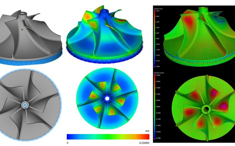
The dimensional assessment of the CT scanned component confirms the dimensional deviations predicted by the Magics Simulation Module, showing that symmetry within the part was achieved.
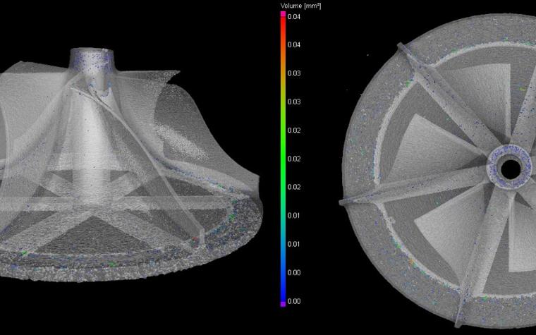
Porosity analysis performed on the CT scanned data in VGSTUDIO MAX indicates that the best parameter set resulted in part porosity of 0.09%, satisfying our goal of 99.9% density. When we visualized the porosity in 3D, we found that pores were small and uniformly distributed within the part — the best configuration to improve fatigue life.
The combined use of the Magics Simulation Module and analysis of CT scanned data with VGSTUDIO MAX enables us to quickly find the printing parameters that minimize local porosity and improve part quality.
The result
By linking X-ray computed tomography data to engineering designs and simulation, we are able to quickly identify the best file preparation parameters and 3D print this challenging part in only a few weeks’ time. We have reconfirmed that this part has been printed accurately and with minimal porosity. Thanks to the combined use of software from Materialise and Volume Graphics, the impellers are more likely to last in the long term. By exploring innovative solutions, we’re always working to ensure that users of 3D printing software get the best quality out of their production facilities.
Share on:

Meet the author
Tom Craeghs
You might also like
Never miss a story like this. Get curated content delivered straight to your inbox.