CASE STUDY
Materialise 3-matic Makes Topology Optimization More Attractive
A university graduate student wanted to use topology optimization to minimize the volume and weight of an aircraft engine bracket. However, it was taking too long to convert optimized files back to a CAD format: until he tried 3-matic.
Industry
Aerospace
Key solutions
Materialise 3-matic
The impact
Reduce processing time of TO results from days to hours
Elaborate smoothing and repair functions, volume meshes
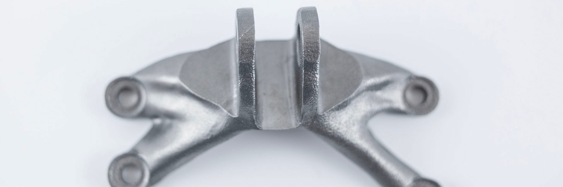
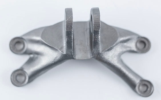
General Electric recently hosted a contest to create an engine bracket and KMWE, supplier and partner for the high-tech equipment industry and aerospace, accepted the challenge. Max van der Kolk, a master’s student at the Delft University of Technology in the Netherlands, based a project on this case from KMWE and did the research at TNO (Dutch Organization for Applied Scientific Research). His goal was to optimize an existing aircraft engine bracket to minimize the volume of the component and significantly reduce its weight.
Max wanted to achieve this by using topology optimization, a technique that reduces weight, but maintains strength. He researched the development of an efficient workflow which allows to post-process conceptual designs developed with topology optimization. Thanks to Materialise’s software, he was able to surmount some problems on his way.
The main bottleneck
The main problem that engineers who want to use topology optimization encounter today, is that it takes a lot of time to convert the optimized files back to a computer-aided design (CAD) format. This makes a direct transition between the concept generation and the concept development phase impossible. Consequently, a significant amount of effort is required to manually convert the topology-optimized results to a suitable CAD file. This ineffective method creates a discrepancy between the initial, optimal solution and the result. Max determinately looked for solutions that allow efficient implementation of topology optimization in industrial applications.
Dreaming of the ideal solution
The main goal was to find a way to import the topology-optimized results to CAD assemblies. “The concept development phase is usually where the most problems occur and the workflow often comes to a halt, resulting in manual interpretation or remodeling of the obtained conceptual solution,” explains Max. Therefore, he made a list of the main software requirements:
- The files obtained using topology optimization contain many rough surfaces, so making modifications directly applied at the STL level is required. Smoothing, repairing and modifying the rough surface will result in much better surface quality and manufacturability of the design. It prevents complicated surface descriptions when moving to CAD, as well as more complexity and possible stress concentrations for the strength analysis (FEA).
- The software package should be able to create CAD compatible files. For this scope, specific modifications to the STL files are required.
- Finally, the package should be able to interpret the STL format and create both a surface and a volume mesh. In order to create a sufficient mesh, the object needs to be smoothed.
Selection of the best-suited software package
The thesis student evaluated multiple existing software packages and was happy to discover that one software package had all the features he was looking for. Materialise was proud to hear that its Materialise 3-matic package was, according to Max, “The best-suited and most efficient method in post-processing these topology-optimized results.”
A more efficient workflow
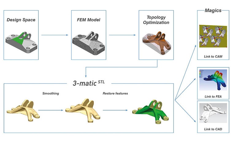
- First the engine bracket was contained in a raw STL file. The formats were imported directly to the topology optimization software and the object was placed in the design space.
- Then the bracket was topologically optimized. The surface was smoothed and errors were repaired, while preserving detailed features.
- The next step was to export the structure to a NURBS or CAD file. Max notes that the step towards CAD formats is not always necessary. When additive manufacturing is used as the main fabrication method of the design, conversion to a CAD file can be left out. On the NURBS file you do a Finite Element Analysis (FEA) to analyze the strength of the object. For his research, he exported the NURBS representations towards CAD with Materialise 3-matic and the results illustrate complete compatibility.
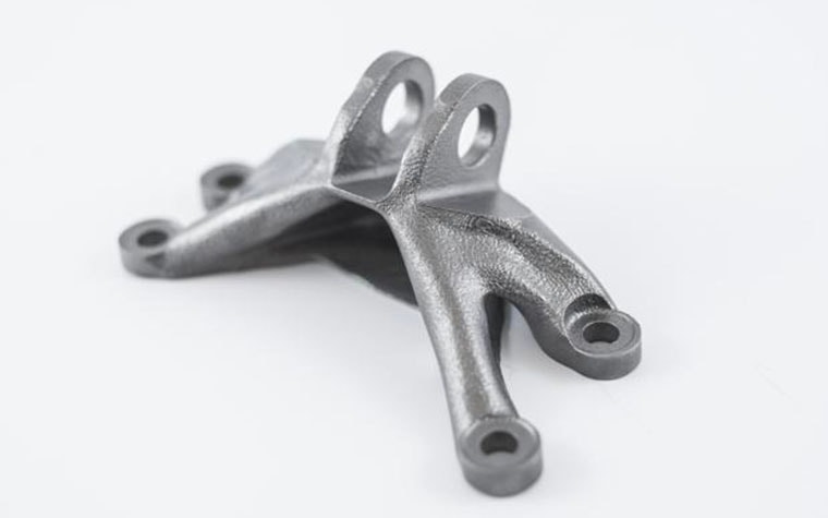
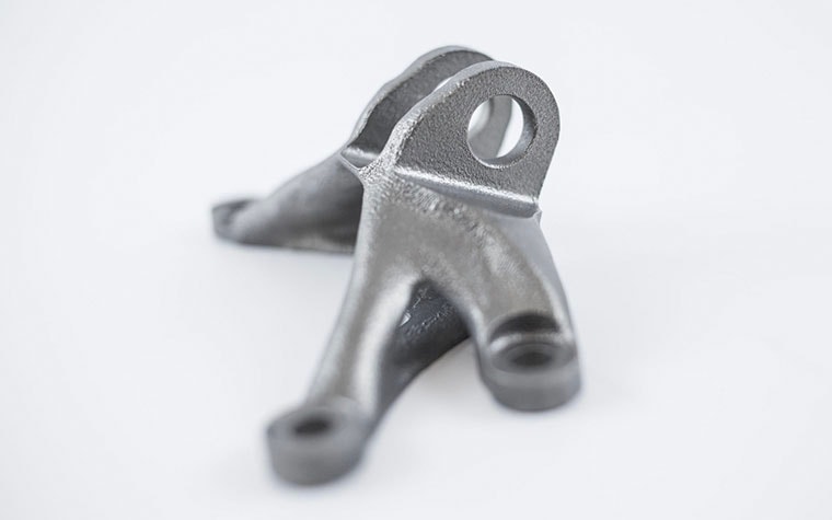
- The Materialise 3-matic Remesh Module provides the ability to convert the surface meshes of the structure into volume meshes. It is verified that the obtained volume meshes corresponded to the design. “The mesh of the structure can be completely prepared with Materialise 3-matic,” explains the future engineer. When the structural analysis was satisfied, the design within Materialise 3-matic could be directly sent off to be printed with computer-aided manufacturing (CAM). Compatibility with Additive Manufacturing was proved by 3D printing two small scale models of the engine bracket.
A great success
Max’s research has shown that the Materialise 3-matic package is able to perform all post-processing steps defined in the described workflow. It can transform scanned measurements to CAD files and develop volume meshes for FEM analysis.
“Compared to other methods the proposed workflow is able to reduce the required post-processing time from days to hours for the considered bracket,” asserts Max. “Materialise 3-matic contains more elaborate smoothing and repair functions than other software packages. The surface processing and creation of volume meshes give this package an advantage above the competition,” he adds. “In addition, the cost of the Materialise 3-matic package is significantly lower.” Thanks to innovative software packages such as Materialise 3-matic topology optimization is more attractive and valuable time can be saved.
Featured products and services
Share on: