EXPERT INSIGHT
Reduce Scrap, Build Failures, and Costs for Metal LPBF with Magics' 3D Printing Simulation Module
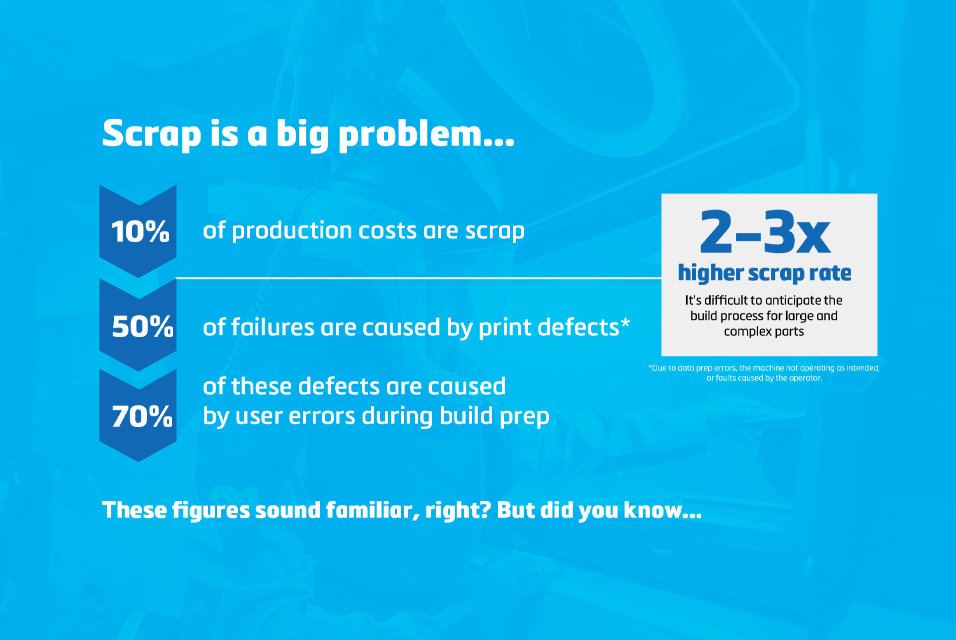
Failed 3D printing builds are an unfortunate reality of our industry, and their impact can be significant. In fact, they often account for as much as 10% of production expenses. It's much more than just wasted material — it's wasted machine time, pre-print efforts, energy, and more. So, what if we could predict these failures and intervene before it's too late? That's where additive manufacturing simulation software comes in, offering a practical solution to one of the most costly aspects of metal laser powder bed fusion (LPBF) 3D printing.
The hidden costs of failed builds
When not done efficiently, the costs of metal additive manufacturing (AM) can get out of hand quickly. It's a hurdle that holds many back from expanding into this manufacturing technique.
Large, complex parts are two to three times more vulnerable to build failure. The larger the build area, the higher the residual stress. This makes it more difficult to predict and maintain control over your build.
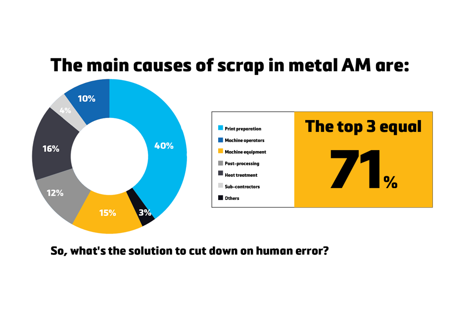
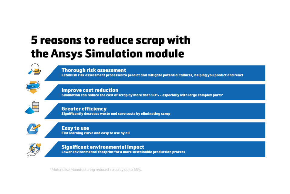
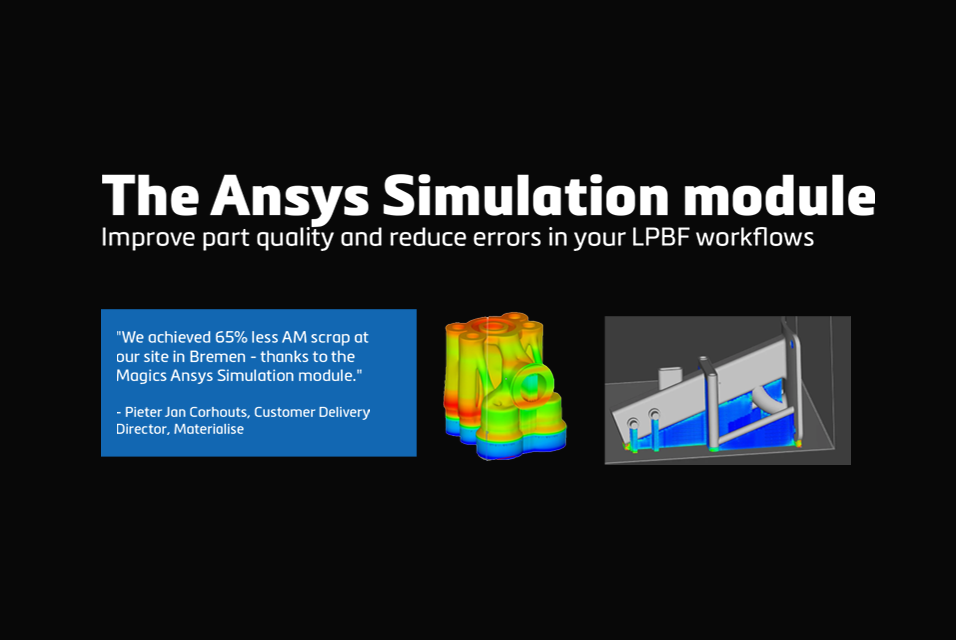
When we break it down, 50% of failures are due to print defects, 70% of which stem from preventable user errors. By introducing additive manufacturing build simulation tools, such as the Ansys Simulation module in Materialise Magics, you can identify problem areas, address them proactively, and significantly lower the scrap rate.
Start with the right questions
Successful builds start with a thoughtful approach to part preparation. As part size and complexity increase, this preparation becomes increasingly critical. Before diving into design, ask yourself the following questions.
- Can I print this model at the desired size?
Metal LPBF is perfectly capable of larger prints, but it's important to evaluate whether your part's dimensions are realistic. There could be deformation risks or additional steps you need to include in the process. - Is post-treatment necessary?
Some materials, like titanium and Inconel, require treatment after printing to relieve residual stress and achieve dimensional accuracy. Understanding whether heat treatment is necessary early on helps you plan accordingly. - Will my support structures be strong enough?
The residual stress caused by extreme changes in temperature doesn't just affect the part itself; it also impacts the support structures. Ensure that your supports are robust enough to handle it. If you still have doubts, consider adding more structures or strengthening the existing ones.
How do build failures impact your business?
Flawed builds don't just impact individual parts — their effect cascades down through more aspects of your business.
Dimensional deviations
Your customers expect and deserve parts with the exact dimensions they request, especially in demanding industries like aerospace and healthcare. Even minor inaccuracies can require reprints, and they can damage your reputation with your customers.
Build issues
Your build is complete, you start unloading the printer, and you notice a defect. Not just on one part, but the issue has rippled throughout the entire build. These setbacks leave your customer, or multiple, waiting longer than expected.
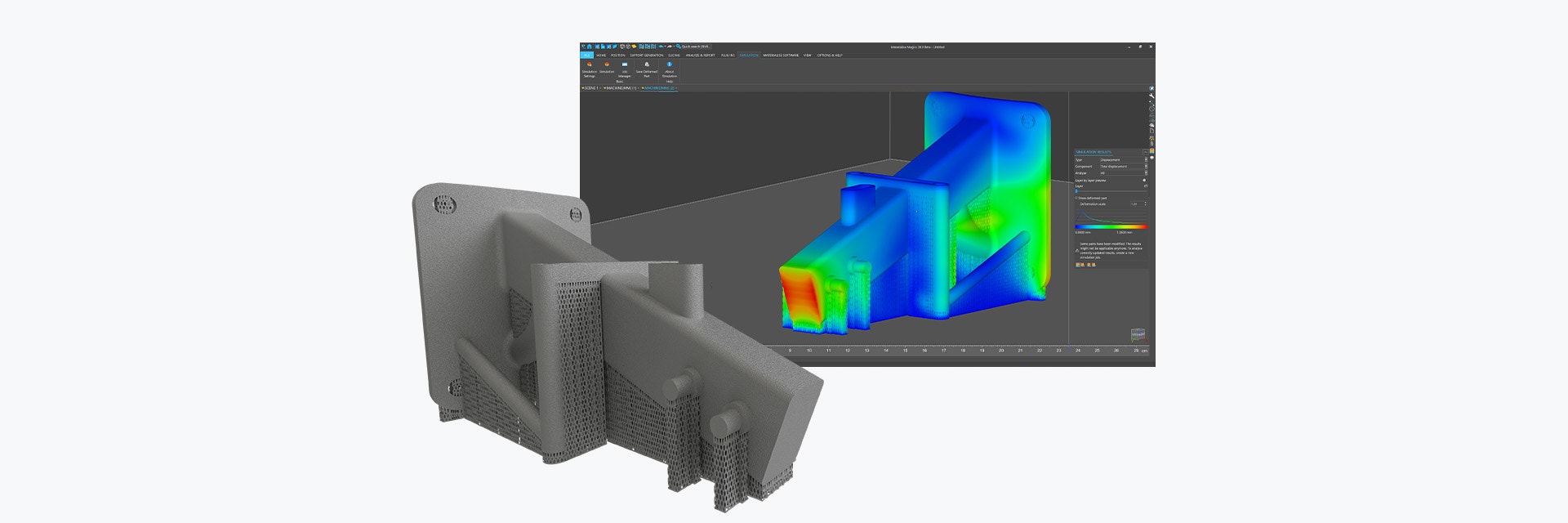
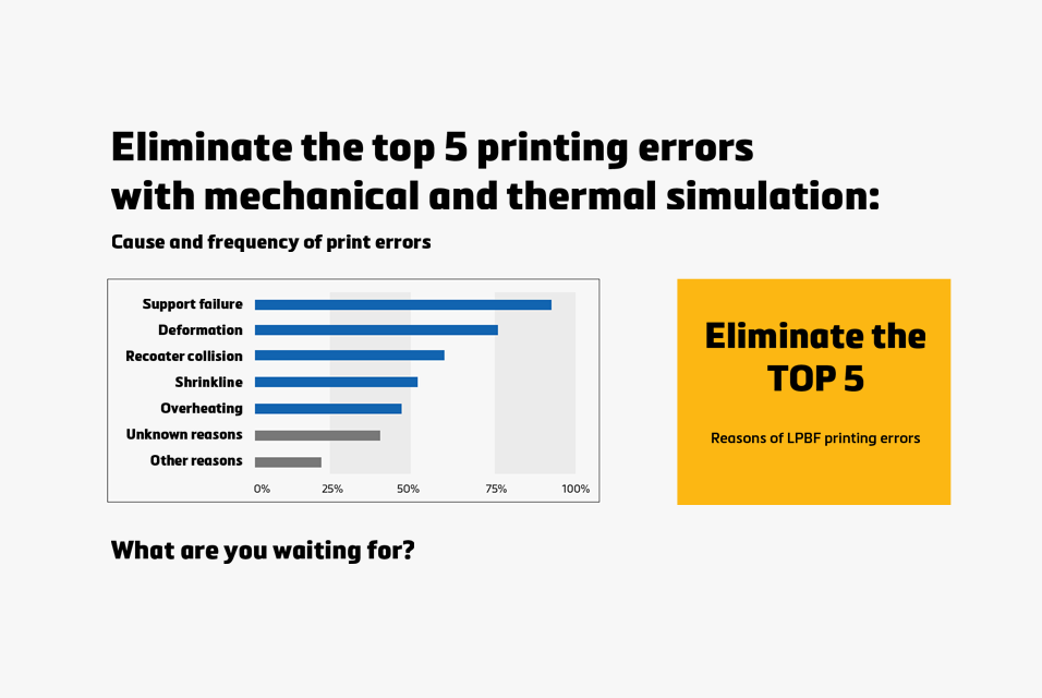
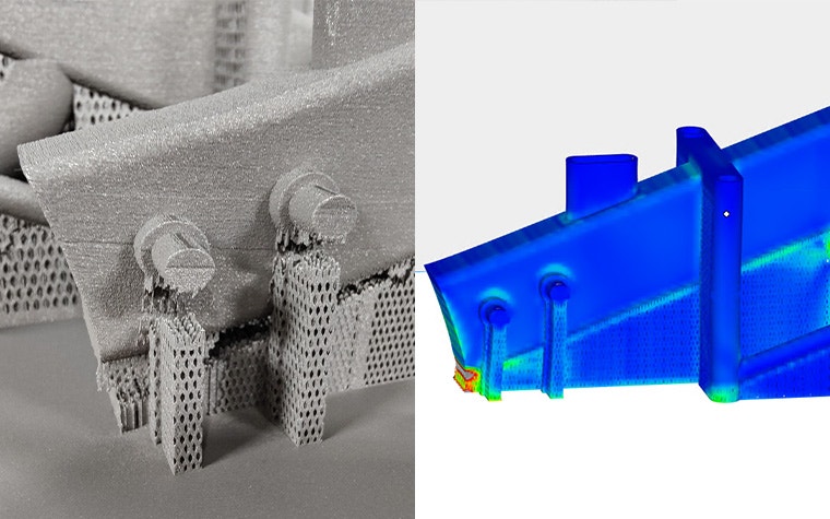
3 flaws you can predict with simulation
There are three commonly recurring issues in LPBF that you can identify with 3D printing simulation software: part deformation, support breakage, and shrink lines. Let's take a closer look at each.
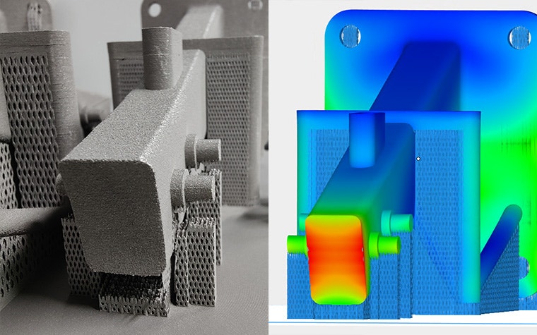
1. Part deformation
Residual stress can cause your parts to warp. This may lead to a final product that doesn't meet design specifications or customer expectations.
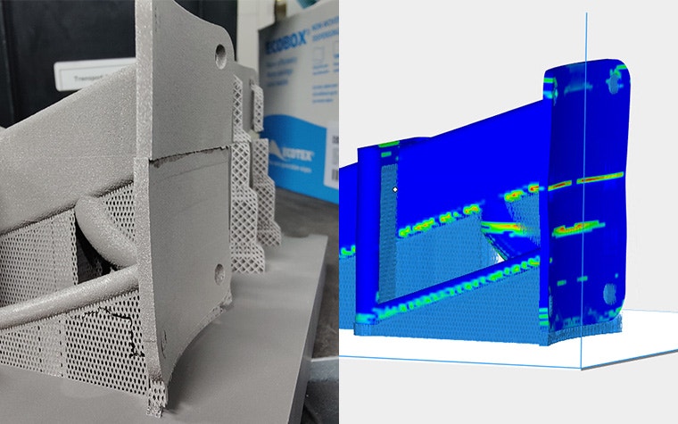
2. Support breakage
As mentioned above, residual stress also jeopardizes the integrity of support structures. Weak or broken supports can detach from the part during printing, compromising the entire build.
3. Shrink lines
Shink lines occur when material inadvertently forms a bridge-like connection, causing misalignment in the x-y plane. This creates a visible defect in the form of a line on your final part. There is also a deformation similar to shrink lines that happens when a support structure breaks, slightly shifting the part and resulting in a visible horizontal line.
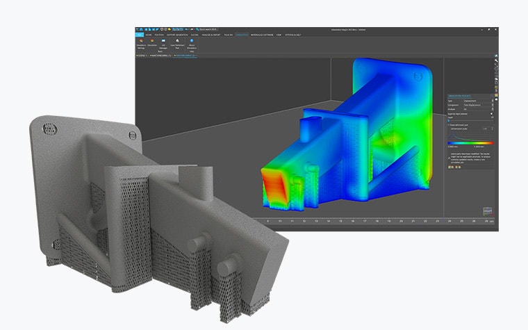
Gain confidence with simulation tools
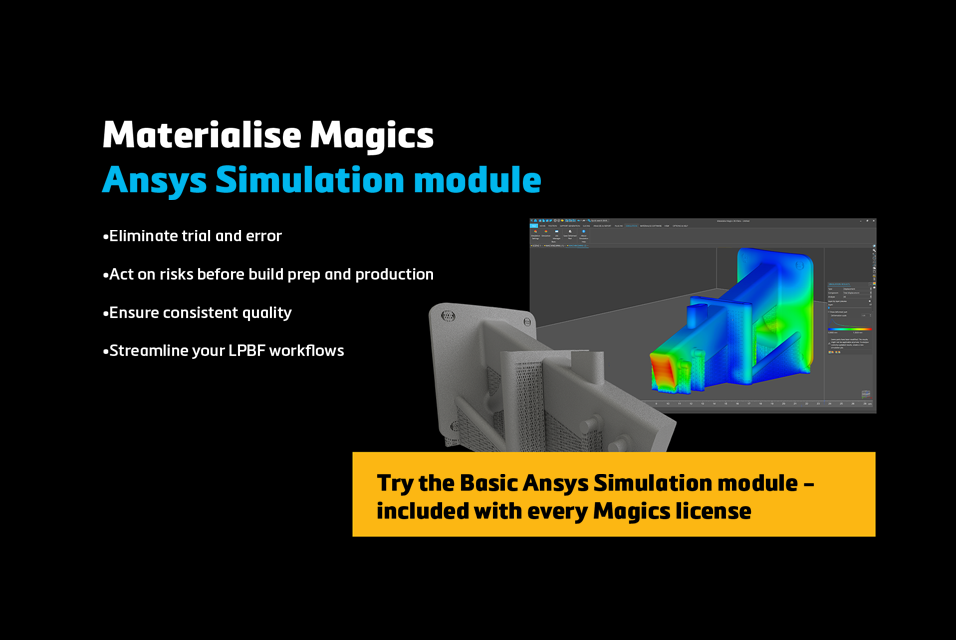
If you recognize these challenges, simulation offers a clear path forward. And if you're already using Magics, you have access to a free version of our Ansys Simulation module. This offers uncalibrated simulations for various metals, allowing you to estimate total displacement and assess whether your design is likely to print successfully. While they're not tailored to your specific printer, these insights provide a reliable starting point and help you make better-informed decisions.
Proactively identify problem areas to refine your designs, optimize support structures, and reduce the likelihood of failure.
Share on:
You might also like
Never miss a story like this. Get curated content delivered straight to your inbox.