DESIGN GUIDELINES
PA-AF (Aluminum Filled)
Wall thickness
In 3D printing, wall thickness refers to the distance between one surface of your part and the opposite sheer surface. For PA-AF (Aluminum Filled), we recommend a minimum wall thickness of 1 mm. High wall thickness can give you a strong solid surface, while lower wall thickness can create a more flexible surface.
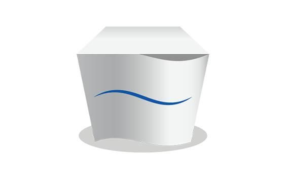
Hollowing
If possible, try to hollow out your part. This avoids deformation and discoloration during the printing process. You can either hollow out your part without a surface hole, which means that unsintered powder will remain trapped inside, or you can design a strategically placed hole (two would be even better) so that the unsintered powder can be easily removed after printing. If the part needs to be reclosed, design a lid with a diameter allowing for 0.5 mm play between the part and the lid.
If your part has walls thicker than 9 mm, our production team may hollow out the part to prevent deformation and discoloration. For parts with wall thickness higher than 20 mm wall thickness, this is done by default. In that case, the powder will stay trapped inside.
Warpage and deformities
We strongly recommend that you do not design large, flat plains in dimensions like an A4 page. In most cases, your model will deform. This process is called “warping”. Creating support ribs under your plane does not solve the problem, but rather increases the chance of deformation even more. The key here is to avoid large flat planes.
Interlocking or moving parts
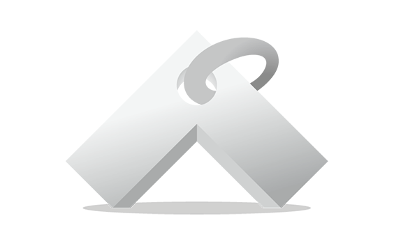
It is possible to print interlocking and moving parts or single-build assemblies in PA-AF (Aluminum Filled). Parts that are printed together should have a minimum clearance of 0.5 – 0.6 mm. If you want to print a chain, spacing between your surfaces is crucial. The more space you can afford, the better. The more complex your part is, the more difficult it becomes for us to evacuate unsintered powder from the interior when the part is taken out of the 3D printer. Please get in touch with our team before ordering parts of this kind to ensure printability and avoid disappointments.
Assembly
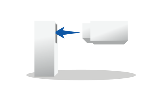
When designing parts that need to be assembled, it’s important to maintain enough distance between the parts. A perfect fit in your CAD software does not necessarily ensure a perfect fit after printing because your software ignores the friction present in the real world. Therefore, always leave at least 0.6 mm between the different parts. For parts with large surfaces and wall thicknesses, you will need to maintain even more distance between the parts. In cases like these, please get in touch with our team to check printability.
In order to help us print your parts with the best possible dimensions for assembly, please design your files with an orientation equal to the relative orientation of your parts in the final assembly.
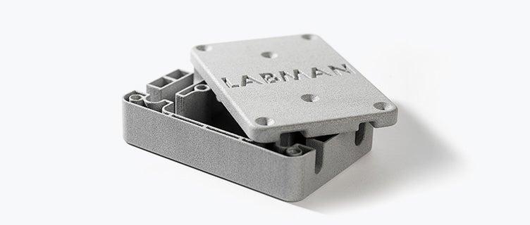
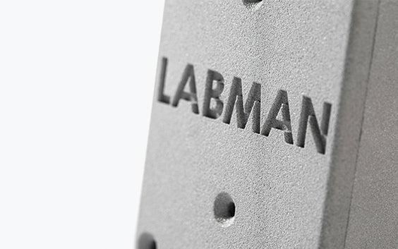
Embossed and engraved details
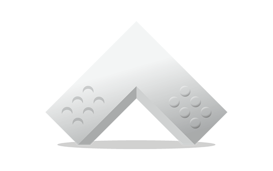
For engraved text or surface details, we recommend letters with a minimum line thickness of 1 mm, a depth of 1.5 mm, and an overall height of at least 4.5 mm. Embossed text or surface details should be thick enough that they will not break during production or transport. We recommend letters that have a line thickness of at least 0.8 mm, an overall height of at least 3 mm, and a depth of at least 0.8 mm.
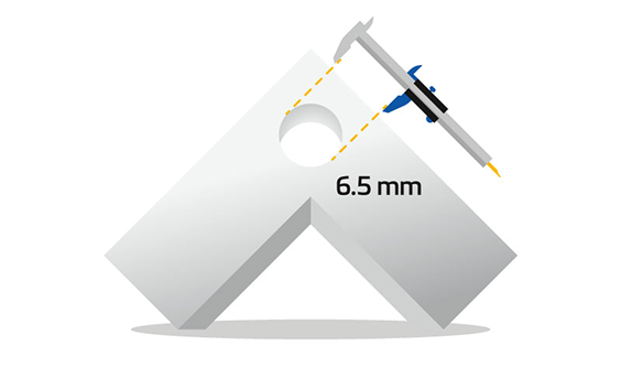
Holes and channels
Holes with a small diameter are exposed to a lot of heat during the sintering process. This can cause the powder inside the holes to become fused. To make sure that holes in your parts remain clear, design a diameter of at least 1 mm.
Longer internal channels can be difficult to clear out, especially if the powder is partially sintered together. We recommend a diameter of at least 3 mm for internal channels. In the case of complex channel geometries with several turns, please get in touch with our team to check printability.
Milling
PA-AF parts can be easily milled, unlike parts printed with PA 12.
Hinges and springs
PA-AF is a harder material than PA12 (SLS), but it is also more brittle. These characteristics make PA-AF unsuitable for flexible parts, hinges, and springs; these applications are better served by PA12 (SLS).
Sealing: Accessibility
Due to the process described above, surfaces that cannot be accessed easily will most likely be treated less, leading to a lower level of sealing. For internal channels, make sure that the diameter is above 6 mm or the channels could get blocked with sealing agent.
Sealing: Watertightness
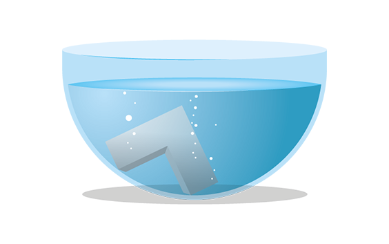
Please be aware that the sealing agent improves how watertight your design is but does not guarantee a fully watertight product as this depends on several circumstances: the complexity of your design, the temperature of your surroundings, the pressure used, the liquid used etc. We recommend this finish for decorative use and advise testing your application first before fully using it.
File requirements
We accept file formats STL, 3DS, 3DM, OBJ, WRL, MATPART, STP, SKP, SLDPRT, STEP, CATPART, IGES, MODEL, MXP, and MGX on Materialise OnSite.
As well as the need to respect these file formats, there are also constraints related to the content of those files. To deliver the best possible quality and ensure traceability, we only allow one model per part to be ordered via our online platform OnSite.
This means per file, there can only be one shell. If there are multiple shells in one file, we will only process it as it is recognized as one model or part meaning that the shells are intersecting or interlocking each other (if applicable see the technical specifications below). Otherwise your part will not be processed correctly.
Technical specifications
| Maximum part dimensions | 630 x 330 x 550 mm |
| Standard accuracy | ±0.3% (with a lower limit of ±0.3 mm) |
| Layer thickness | 0.15 mm |
| Minimum wall thickness | 1 mm |
| Minimum detail size | 0.3 mm |
| Interlocking or moving parts | Yes |
| Internal channels | Yes |
| Surface structure | Grainy structure |