DESIGN GUIDELINES
PA-CF
Wall thickness
In 3D printing, wall thickness refers to the distance between one surface of your part and the opposite sheer surface. A part that would fit a box of 250 x 250 x 300 mm, needs to be designed with a minimal wall thickness of 1 mm. The walls of larger parts need at least 1.5 mm thickness.
However, overly thick walls are not advisable either as they use more material than you need and run the risk of deforming the part. If your design has wall thicknesses greater than 6 mm, we fill the wall thickness with sparse structures. This helps us save material and minimize the likelihood of warpage.
Surface quality and orientation
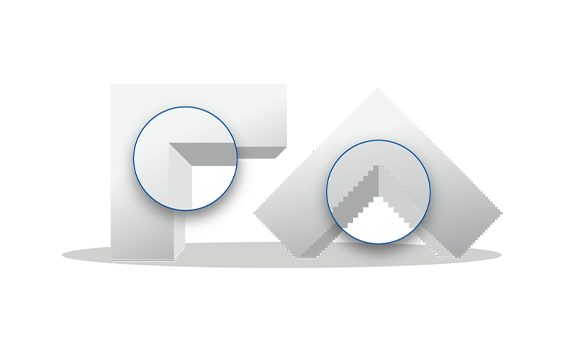
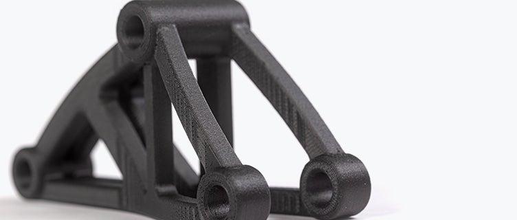
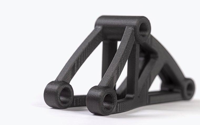
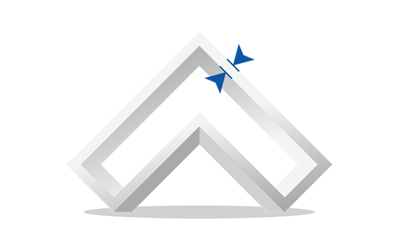
Many of the characteristics of your 3D print will depend on the fused deposition modeling (FDM) process. Because your part will be printed layer by layer, the printing orientation will influence its surface quality and strength. In the illustration, you can see two parts of the same shape but built with different orientations.
The horizontally printed model clearly shows the “staircase” effect of the printing process. Its surface will be similar to that of a topographic map. If the part is printed vertically, the surface quality will be better.
Think about which surface needs to have the best finish and choose the orientation accordingly when printing.
Anisotropy
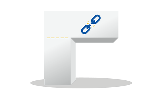
Because your part is built up layer by layer, it will always have “weak points” caused by its printing orientation. These weak points can cause thin external elements of your design to easily break off. Therefore, avoid features on your part that are parallel to the base or bottom plane and that will require strength to support them.
Dimensional accuracy
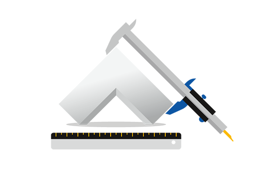
FDM is one of the 3D printing processes (for plastics) with the highest dimensional accuracy. Dimensional accuracy does not relate to the detail of your part but to the deviation from the nominal size. The standard accuracy we offer for PA-CF is 0.15% with a lower limit of ±0.2 mm. Z part accuracy includes an additional tolerance of -0.000/+ slice height (0.254 mm).
Support
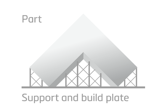
Fused deposition modeling takes place on a building platform. Since parts will be “built in mid-air”, they must be attached to the supporting platform to prevent them from collapsing. This attachment is referred to as the “support” and is required for any part built using this technology.
In addition to keeping the part in place, it also enables the construction of overhanging elements. After the building process is complete, the support is manually removed.
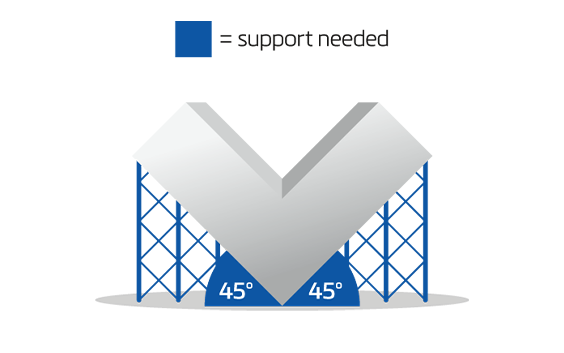
External support
Parts that have sections narrower than 45° must be supported. The support is required to keep your part in place and prevent it from collapsing while being printed. In the the illustration, the bottom of the part must be supported because it is narrower than 45°. The rest of the design doesn’t require extra support because it is wider than a 45° angle.
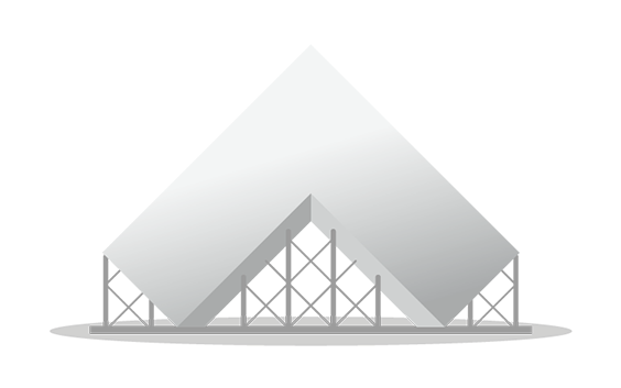
Internal support

The 45° rule also applies to the interior of your part. Any model with an interior section below 45° must be supported. In the illustration, the model on top must be supported to prevent it from collapsing during the printing process.
Rule of 30°
This illustration shows you when a part requires support. The “self-supporting” or “safe” zone does not require any support to print the part. For most parts, this area ranges from 135° to 45°. When designing an object you would like to print in PA-CF, keep this safe zone in mind if you are concerned your part will require support to be constructed.
Interlocking or moving parts
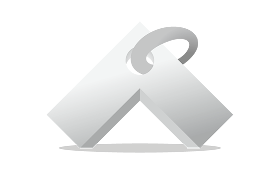
It’s possible to print interlocking and moving parts — like a wrench or a ball bearing — in PA-CF because the support material used for PA-CF is water-soluble. Parts that are printed together should have a minimum clearance of 0.4 mm.
Embossed and engraved details
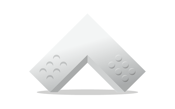
In general, engraved text or details are preferable to embossed text or details. For engraved text or surface details, we recommend letters with a minimum line thickness of 1.2 mm and a depth of 0.5 mm. For embossed text and surface details, we recommend that letters have a line thickness of at least 2.5 mm and a depth of at least 0.5 mm.
File requirements
We accept file formats STL, 3DS, 3DM, OBJ, WRL, MATPART, STP, SKP, SLDPRT, STEP, CATPART, IGES, MODEL, MXP, and MGX on Materialise OnSite.
As well as the need to respect these file formats, there are also constraints related to the content of those files. To deliver the best possible quality and ensure traceability, we only allow one model per part to be ordered via our online platform OnSite.
This means per file, there can only be one shell. If there are multiple shells in one file, we will only process it as it is recognized as one model or part meaning that the shells are intersecting or interlocking each other (if applicable see the technical specifications below). Otherwise your part will not be processed correctly.
Technical specifications
| Maximum part dimensions | 914 x 610 x 914 mm 406 x 355 x 406 mm (online orders) |
| Standard accuracy | ±0.15% (with a lower limit of ±0.2 mm) |
| Layer thickness | 0.330 – 0.508 mm 0.33 mm (online orders) |
| Minimum wall thickness | 1.4 mm |
| Minimum detail size | 0.6 mm |
| Interlocking or moving parts | Yes |
| Internal channels | Yes |
| Surface structure | Rough, matte surface with visible layers |