
DESIGN GUIDELINES
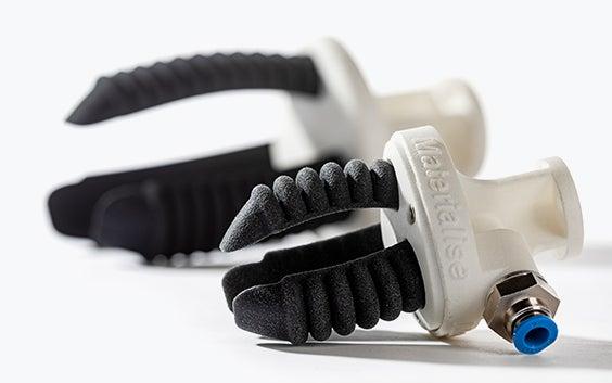
Ultrasint TPU 90A-01
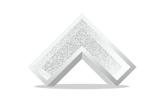
Wall thickness

In general, we recommend a wall thickness of at least 1 mm. Large parts may require larger wall thicknesses or added ribs or fillets for reinforcement.
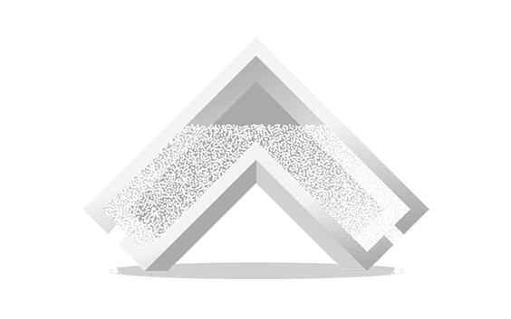
Hollowing
We advise hollowing out a solid model as much as possible, and when the wall thickness exceeds 20 mm. We recommend a wall thickness of 1-2 mm and the inclusion of at least two holes with a minimum diameter of 10 mm for powder removal.
Holes and channels
It is possible to create holes or perforations and internal channels. For holes and perforations, the recommended minimum diameter size is 2 mm, but some post-production will be needed to remove excess powder.
Longer internal channels can be difficult to clear out, especially if the powder is partially fused together. In general, complex holes or ducts require larger diameters to achieve thorough removal of the unfused powder. We recommend a diameter of at least 3 mm for internal channels. Some residual powder may be stuck on the inside of complex channels. It is advised to design a strip or chain through the channel to help in dislodging the powder once the part has been printed.
Interlocking or moving parts

It is possible to print interlocking parts and assemblies in a single build. Parts that are printed together should have a minimum clearance of 0.5 mm.
Lattice structures
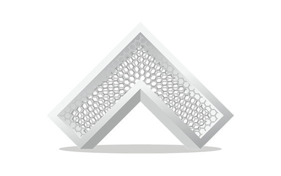
Lattice structures allow you to modify shock absorption characteristics, as well as to reduce weight and material. Keep in mind that you must maintain a minimum gap of 5 mm between the lattice beams so the unfused powder can be removed.
Embossed and engraved details
For embossed or engraved textures, we advise a minimum thickness of 0.25 mm. For legible engraved or embossed text, we recommend letters with a minimum line thickness of 0.5 mm, a depth of 1 mm, and an overall height of at least 2.5 mm.
File requirements

We accept file formats STL, 3DS, 3DM, OBJ, WRL, MATPART, STP, SKP, SLDPRT, STEP, CATPART, IGES, MODEL, MXP, and MGX on Materialise OnSite.
As well as the need to respect these file formats, there are also constraints related to the content of those files. To deliver the best possible quality and ensure traceability, we only allow one model per part to be ordered via our online platform OnSite.
This means per file, there can only be one shell. If there are multiple shells in one file, we will only process it as it is recognized as one model or part meaning that the shells are intersecting or interlocking each other (if applicable see the technical specifications below). Otherwise your part will not be processed correctly.
Technical specifications
| Maximum part dimensions | 370 x 274 x 375 mm |
| Standard accuracy | ±0.9% (XY) up to ±1.8% (Z) with lower limits on ±1 mm (XY) up to ±1.5 mm (Z) |
| Layer thickness | 0.1 mm |
| Minimum wall thickness | 1 mm |
| Minimum detail size | 0.5 mm |
| Interlocking or moving parts | Yes |
| Internal channels | Yes |
| Surface structure | Grainy structure with stone-gray color |