DESIGN GUIDELINES
Inconel (IN718)
Wall thickness
In 3D printing, wall thickness refers to the distance between one surface of your model and the opposite sheer surface. For the Standard Grade, the minimum wall thickness you can use is 1 mm; for the Performance Grade, the minimum wall thickness is 0.5 mm. However, the applicable minimum wall thickness might vary as it depends, amongst other factors, on the part’s geometry and size. Therefore, we recommend a thickness of 2 mm to create structural walls or features.
There is no maximum wall thickness as such but keep in mind that thicker areas may increase stresses in your part, which could cause deformations and might lead to unstable build processes.
Detail size
Very fine details (as small as 0.5 mm) are possible when 3D printing with Inconel (IN718). Detail sizes refer to the distance between the surface of your model and the surface of your detail.
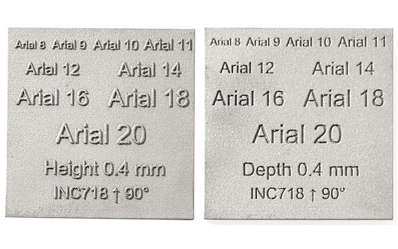
Embossed and engraved texts are also considered as details, but as the printability and readability depend highly on the print orientation, we can only give a general guideline for embossed and engraved text; use Arial 20 pt with 0.4 mm height and depth.
As it is difficult to predict results for all possible fonts, Arial 20 pt corresponds to characters with a line thickness of 0.7 mm and a minimum overall text height of 5 mm. To illustrate what you can expect, please refer to the examples below of embossed and engraved text in the most favorable orientation.
Surface quality and orientation
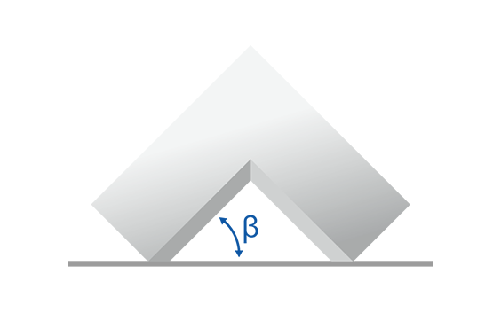
The buildup direction of a part has a large impact on the surface quality as it defines the orientation of the part’s surfaces with respect to the horizontal plane or build plate. Angles (β) measuring less than 45° with reference to the build plate tend to lead to poorer surface quality, while steep angles of more than 45° are likely to have better, smoother surfaces. An overhanging structure (e.g. the underside of a table) is likely to have poor surface quality.
Threads
Thermally induced stresses
Your model in Inconel (IN718) is 3D printed using metal 3D printing, which is basically a layer-wise welding process. The layer-wise powder melting and its solidification leads to thermally induced stresses when the melted powder cools down.
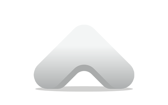
A design that is not suitable for metal 3D printing can lead to build failures and/or part deformations due to large thermally induced stresses. It is therefore essential to consider the process-specific restriction while designing the part. We advise you to round off or fillet the edges in your design with a minimum radius of 3 mm. Also, avoid sharp edges for the same reason. Try to avoid large material accumulations and, in general, favor organic shapes over edged designs.
Dimensional accuracy
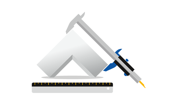
Dimensional accuracy does not relate to the detail of your model but to its deviation from the nominal measurement. The general accuracy for 3D-printed metal is better than or equal to the industry standards DCTG 6 of DIN EN ISO 8062-3: 2008-09 for dimensions between 0.5 and 30 mm, DCTG 8 of DIN EN ISO 8062-3: 2008-09 for dimensions between 30 and 400 mm and DIN ISO 2768 -1 c (coarse) for dimensions between 0.5 mm and 400 mm.
If you are not familiar with these norms, see the table below for an idea of the tolerance you can expect per dimensions as well as the IT grade according to ISO 286.
Note that form deviations might also occur due to designs that are not suitable for metal 3D printing and to high thermally induced stresses.
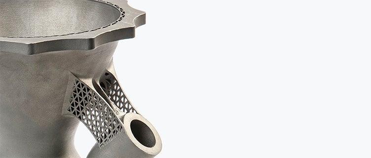
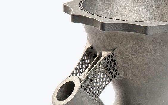
Support
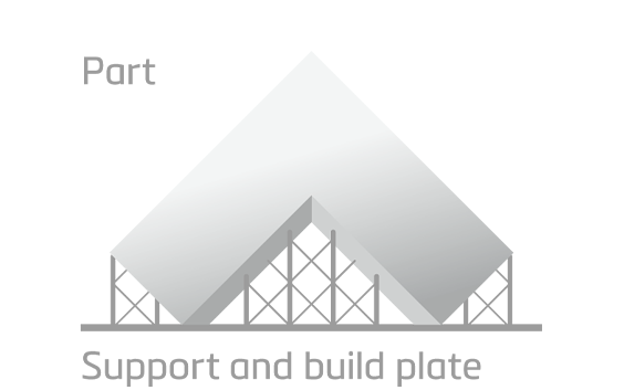
Metal 3D printing is a layer-wise manufacturing process. The part is built up layer by layer according to a digital file. Depending on the part surface’s orientation, support structures might become necessary which also have to be printed in the manufacturing process.
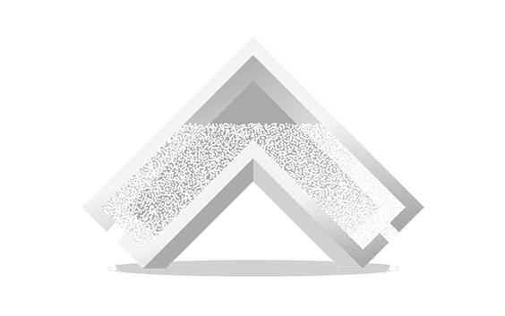
The support structures keep your model rigidly connected to the build platform during the printing process and absorb internal stress, while also preventing part deformations. Walls or overhangs with angles measuring below 45° with reference to the build platform typically need to be supported as they would otherwise lead to building errors. After the part is successfully built, the support is removed and the part is sandblasted. Some evidence of the removed support structures may still be visible.
Powder removal
When making a hollow model, it is important to include at least one hole in your design so that the unused powder trapped inside the cavity can be removed. Try to use a minimum wall thickness of 1 mm and keep at least one opening with a minimum diameter of 3 mm. This opening will serve as an exit for the unused powder trapped inside the printed part. Larger and complex cavities need multiple holes with larger diameters, preferably 7 mm.
Holes in the center of your model are usually the best as they allow most of the powder to be removed. Powder traps in hollow part sections must be avoided in order to allow for complete removal of the powder inside the hollow section.
Although the printing process itself allows us to produce air- or water-tight items, we do not guarantee the air- or water-tightness of the printed parts, as this depends on more factors than the wall thickness and the pressure that will be applied. We therefore recommend testing your individual application for functionality.
Holes
The minimum recommended diameter for a hole is 2 mm. This is the minimum diameter needed to remove internal powder; if the hole is smaller the powder will get stuck inside the geometry. Complex and irregularly shaped holes or interior spaces are impossible for us to inspect or remove the powder completely.
The longer and more complex you make the internal channels, the larger the minimum diameter you have to maintain. A print result according to the CAD geometries therefore cannot always be guaranteed in such cases. We strongly recommend that you avoid designing long internal channels in metal 3D printing unless you are in contact with a Materialise project manager who can review your files.
For bores with high demands on tolerances, we recommend providing offsets or closing the holes completely for printing. The part can later be post-machined to ensure bores according to the part-specific requirements.
File requirements
We accept file formats STL, 3DS, 3DM, OBJ, WRL, MATPART, STP, SKP, SLDPRT, STEP, CATPART, IGES, MODEL, MXP, and MGX on Materialise OnSite.
As well as the need to respect these file formats, there are also constraints related to the content of those files. To deliver the best possible quality and ensure traceability, we only allow one model per part to be ordered via our online platform OnSite.
This means per file, there can only be one shell. If there are multiple shells in one file, we will only process it as it is recognized as one model or part meaning that the shells are intersecting or interlocking each other (if applicable see the technical specifications below). Otherwise your part will not be processed correctly.
Technical specifications
| Maximum part dimensions | 250 x 250 x 305 mm |
| Standard accuracy | Better than or equal to the industry standards:
See design guidelines for more information on standard accuracy. |
| Layer thickness | Standard: 0.08 mm, Performance: 0.04 mm |
| Minimum wall thickness | Standard: 1 mm, Performance: 0.5 mm |
| Minimum detail size | 0.4 mm |
| Interlocking or moving parts | No |
| Internal channels | Yes |
| Surface structure | Rough surface |