DESIGN GUIDELINES
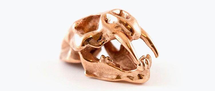
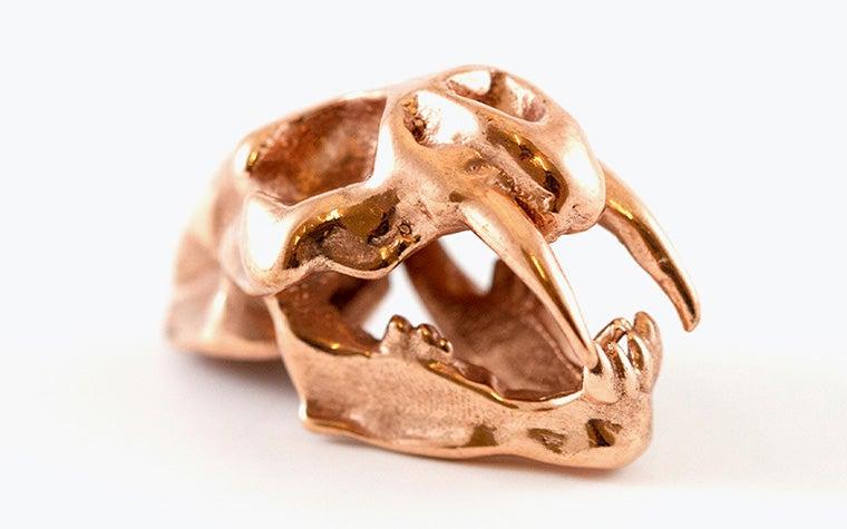
Copper
Wall thickness

In 3D printing, wall thickness refers to the distance between one surface of your model and the opposite sheer surface. For most models in Copper, the minimum wall thickness you can use is 0.8 mm. However, when making something small such as the band of a ring, the wall thickness should be at least 1 mm. The fragility of the Copper might cause the ring to break when you wear it if the model is too thin.
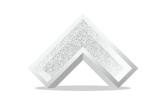
High definition

Since the resolution of the wax printing process is so high, make sure that you create your model and export your file with enough definition so you don’t see the triangles.
Geometry
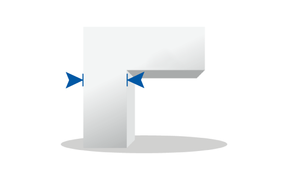
Be careful when having large areas of your model connected or supported by thin rods. Compare it to a big head resting on a thin neck. Your model needs to be designed to adequately support itself, so make sure the rods are strong enough to ‘carry’ the weight of the larger area. Also, it is possible to print internal structures, but removing support structures, cleaning them and casting them can be difficult or even impossible. If you have doubts about whether your model is feasible, please contact us.
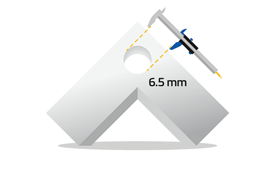
Hollowing
This material allows you to print hollow models. However, keep in mind that you need to incorporate multiple holes or slots so that we can get rid of any unprinted wax resin. Make as many holes or slots as you possibly can. We recommend making two or more holes or slots. Make sure the holes are spread out equally; for example on opposite ends of your design. The holes should have a diameter larger than 1.5 mm. In addition, you will need to make sure that the casting plaster is sufficiently supported or your model will not be able to be cast properly.
Feature size

The smallest features in your design should be at least 0.35 mm in diameter and 0.4 mm in height and attached to a solid surface. Details this small are suitable for delicate projects such as micro pavé settings.
Because Copper is not a very strong material, longer features such as rods or prongs (in mesh-like structures) should be at least 0.8 mm in diameter. Otherwise, they might break during casting or even when you wear the piece.
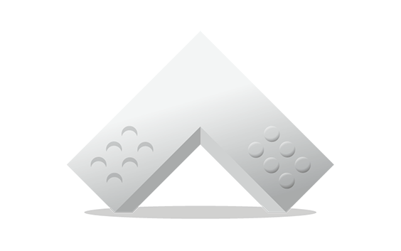
Clearance

The distance or space between two or more parts in your model is called clearance. If there is too little clearance between the parts, they might become fused during the casting of your model. Your model is first printed in wax, placed in a container, and covered in a liquid plaster. Then the wax is burned out, creating a cavity in the now-hardened plaster, leaving a plaster mold ready for casting.
If the gap between the different parts in your model is too small, the plaster may not fully flow in or may create overly-thin walls in the mold that break when liquid metal is poured in. Both of these will result in defects in your casted model. Therefore, we advise a minimum gap of 0.3 mm. If it is impossible to increase the gap in your design, you can consider fusing the features if their separation is unnecessary.
Polishing
In order to polish, we have to be able to reach the surfaces. As a rule, we can't file, sand or polish cavities, and small sharp edges will be rounded off. Also, complex internal, mesh-like structures are impossible to reach.
Nested objects, hinged and interlocking parts

Nested objects (objects floating within another object), hinged parts, and interlocking parts, such as chains, cannot be made with lost wax casting. The reason is that support structures have to be removed before being cast in Copper.
Embossed and engraved details
For embossing or engraving details such as text, we advise you to keep a maximum height/depth-to-width ratio of 1:1. Also, keep in mind the minimum wall thickness of 0.35 mm.
File requirements

We accept file formats STL, 3DS, 3DM, OBJ, WRL, MATPART, STP, SKP, SLDPRT, STEP, CATPART, IGES, MODEL, MXP, and MGX on Materialise OnSite.
As well as the need to respect these file formats, there are also constraints related to the content of those files. To deliver the best possible quality and ensure traceability, we only allow one model per part to be ordered via our online platform OnSite.
This means per file, there can only be one shell. If there are multiple shells in one file, we will only process it as it is recognized as one model or part meaning that the shells are intersecting or interlocking each other (if applicable see the technical specifications below). Otherwise your part will not be processed correctly.
Technical specifications
| Maximum part dimensions | 88 x 88 x 125 mm |
| Standard accuracy | ±5% (with a lower limit of ±0.15 mm) |
| Layer thickness | 0.016 mm |
| Minimum wall thickness | 0.6 mm |
| Minimum detail size | 0.35 mm |
| Interlocking or moving parts | No |
| Internal channels | No |
| Surface structure | Reddish slightly shiny and green oxidated surfaces |