EXPERT INSIGHT
Three Tools that Help Find the Best Orientation for Metal AM Parts
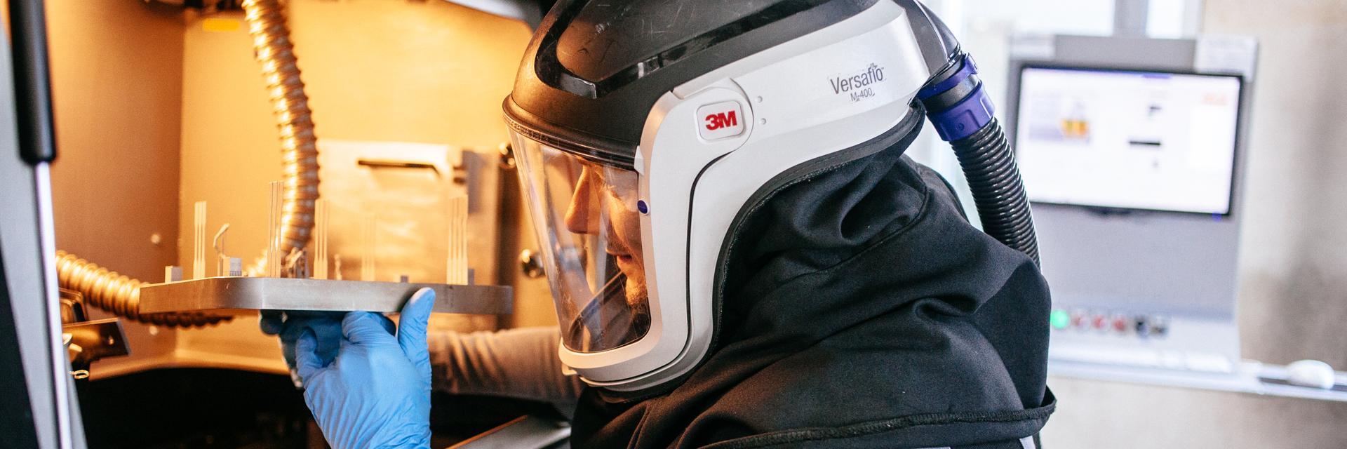
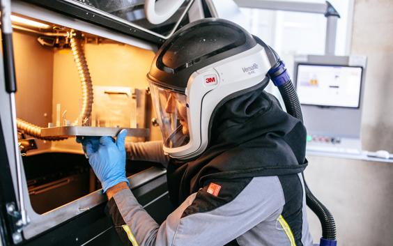
Two years. That’s about the time it takes today to learn how to successfully 3D print metal components. A period characterized by trial and error experiments, build crashes, vaporized money and time, all mixed in with the occasional correct build. To deal with the challenges that metal 3D printing poses, a thorough understanding of how the metal additive manufacturing process works is essential.
The metal process is more than printing the part. It includes powder characteristics, design guidelines, process parameters and post-processing steps. These are all critical components that need to be considered and understood. In this blog post, we focus on the challenges within the metal printing process. The main ones are:
- thermal stresses
- deformation
- shrinkage
These three factors — and thus build success — are hugely influenced by how a data prepper orients a part and generates support structures. And these factors can be controlled and adapted by software. Here are three software tools that will help you get to the best orientation for metal parts.
1. The slice distribution graph
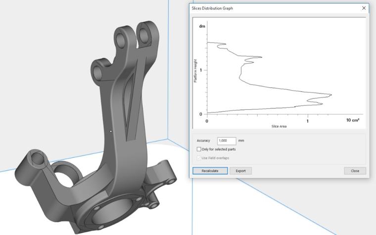
A good part orientation is the first step to a successful build, barring warping or a premature termination of the build process. You can prevent warping by limiting the surface area of each layer and thereby controlling heat build-up. Large differences in temperature between two consecutive layers compromise build quality and can lead to build crashes, so you need a tool that allows them to analyze the surface area for each layer along with the heat distribution within a build.
One of the tools in Materialise Magics is the slice distribution graph tailored for metal applications, which gives you total control of the build process. With the slice distribution graph, you can quickly visualize the surface area per slice to improve part and build quality.
2. The Magics orientation tools
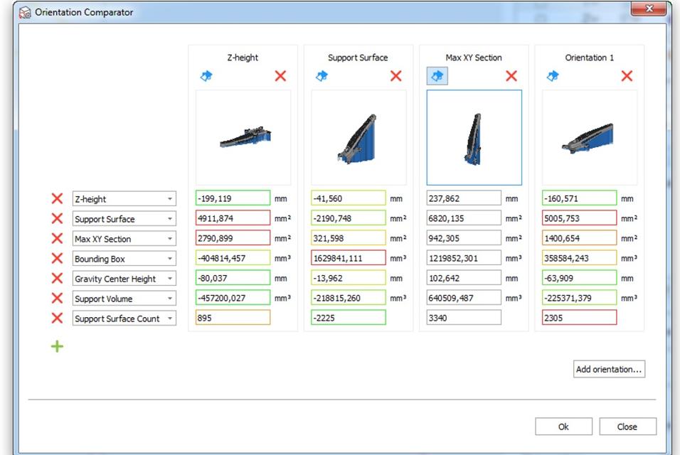
The Magics orientation tools help you orient parts intelligently. This can lead to a reduction of support structures, decreasing material usage and reducing post-processing work. With the orientation optimizer tool, for example, you can mark the zones of the part where they do not want to have any support structures. You are then guided to an orientation in which the zones are self-supporting.
The orientation comparator allows you to compare and analyze in-depth statistics on various orientations making it easy to choose the best fit for your needs.
3. The support preview tool
Depending on your goal, optimal orientation could consist of the right balance between the reduced surface area per layer and the amount of support needed.
The support preview tool gives you a preview of how the support structures might look once generated. The preview is updated in real time during the orientation, cutting down the number of orientation iterations. You can also see an estimation of the volume of your support structure.
Share on:
You might also like
Never miss a story like this. Get curated content delivered straight to your inbox.