CASO DI STUDIO
Predicting Deformations of Titanium Inserts: The Power of Simulation Software
Sandwich panels are used in aeronautics and aerospace applications where high structural rigidity and low weight are required. Together with Atos, a global leader in digital services, we have developed a lightweight titanium insert design for a sandwich panel. The insert design was specifically developed for production with additive manufacturing (AM) and allowed for a 66% weight reduction of the traditional insert design, which has a brick-like shape. We were able to achieve this by creating complex and strong lightweight cellular structures. In this case study, we verify the power of simulation software.

Settore
Aerospace
La soluzione utilizzata
Materialise Magics Simulation software
Le motivazioni di questo approccio
Demonstrate the predictive power of simulation
Compare the measured and simulated deformations
Compare the printed insert to a simulated one
The challenges of printing metallic structures
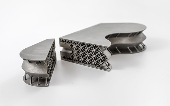
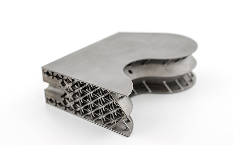
It’s quite challenging to 3D print the optimized insert design since it’s fairly large (366mm x 171mm x 92mm) and contains a complex, lightweight cellular structure connected to the enclosed outer shell of the insert.
During the additive manufacturing process of metallic structures, high temperature gradients develop unwanted residual stresses which cause shrinkage effects in manufactured designs. This is a serious problem since they may lead to part rupture or deformations during the manufacturing process, or introduce part deformations and micro cracks to the final part. Besides the mechanical aspects, it is also important to keep in mind the financial aspect of poorly printed designs. The manufacturing cost of the presented part ranges around €2,500, so a considerable amount of money goes to waste if the printing process fails or the quality of the final part is compromised.
The predictive power of simulation software
Simulations can be used to predict the deformations, residual stresses and temperature evolution in parts during and after the AM process. By facilitating these simulations, you can identify and correct the regions sensitive to failure to increase the chance of a successful build, as well as the overall part quality.
To demonstrate the predictive power of simulation, we used the design of the lightweight insert to simulate the outcome of the printing process. To validate the simulation results, we manufactured and measured the part using 3D scanning after the printing process. Then we compared the measured and simulated deformations.
The workflow:
- We first started with creating a calibration profile for the machine in Magics simulation software. We did this by printing a test specimen and measuring the deformation after removal from the base plate. Next, we used the Magics simulation module to automatically find the right simulation parameters (eigenstrains) for the machine, material and scan parameters.
- We sliced the CAD file and generated a mesh for the design
- We applied the values obtained from step one to the mesh and applied the inherent strains to each simulation layer
- We simulated the support removal and removal from the building plate
- Finally, we compared the final simulated deformation with the original CAD design to identify regions with critical deformations
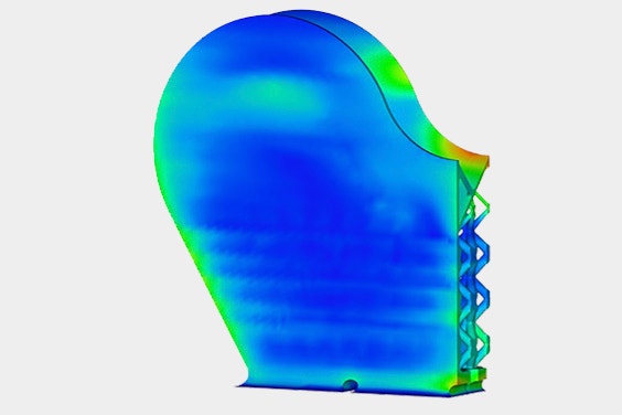
Representation of step 3: simulation of the 10th macro-layer Representation of step 3: simulation of the 30th macro-layer
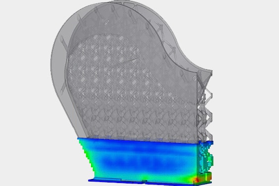
Comparing simulation with printed results
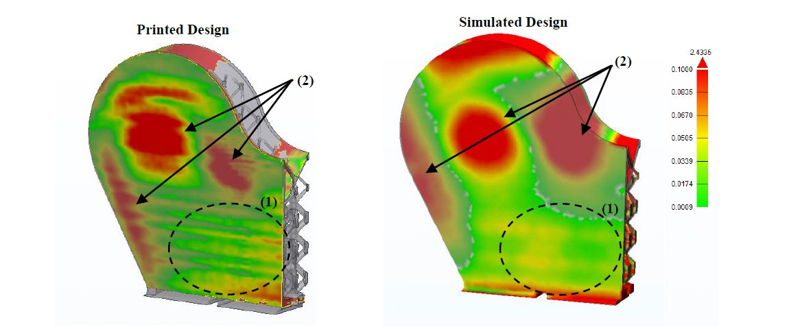
Comparison of the deformation of the printed part vs. the simulated part.
The result was that the deformed regions of the simulated part matched very well with the measured deformed surface of the printed part (scan results). The dashed circles indicate regions with local deformation due to underlying lightweight cellular structures. The arrows indicate global deformations.
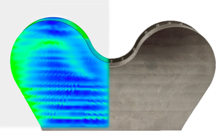
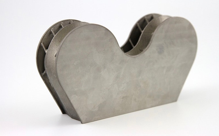
The printed titanium part cut open (image below left) and from the top (image below right) show the local deformations due to the underlying lightweight cellular structures.
The comparison between the deformation of the actual manufactured part and the simulation revealed that simulation software can properly predict regions that (1) experience localized deformation increasing the risk of manufacturing artefacts, as well as (2) global deformations that may compromise the overall part quality. These findings provide valuable process insights to manufacturing and design engineers enabling them to further optimize their metal AM builds.
Condividi su: