CASE STUDY
Automating Key Components of Finite Element Research
Short-stem femoral implants have a smaller contact area with the femur than long-stem implants. To better understand peak stresses and areas of stress shielding, researchers at the University of Leuven and University Hospital of Brussels wanted to use finite element analysis to assess performance across a representative study population.
Industry
Healthcare
Key solutions
Materialise Mimics
The impact
Efficient scaling of work
Automation of repetitive tasks
Larger study population
Case presented by Amelie Sas, MSc, Pim Pellikaan, MSc, and Prof. Harry van Lenthe from the Biomechanics Section, Department of Mechanical Engineering, Faculty of Engineering, University of Leuven, Belgium, and Prof. Thierry Scheerlinck from the Department of Orthopedics and Traumatology, University Hospital Brussels, Belgium
The challenge
Assess short-stem implant performance
In total hip replacement surgery, most traditional designs of femur components have a long stem. Short hip stems have only recently been introduced, and these are presumed to reduce proximal stress shielding compared to traditional, long stems. However, due to their smaller contact area with the bone, high peak stresses and areas of stress shielding could appear in the proximal femur, especially in the presence of atypical bone geometries.
Researchers at the University of Leuven and the University Hospital of Brussels wanted to better understand this aspect by virtually implanting a commercially available calcar-guided short stem implant (Optimys from Mathys AG, Bettlach, Germany) in a series of bones with deviating proximal geometry, and by performing finite element analyses.
To investigate the performance of short stem implants across a wide range of femurs, a large number of finite element models had to be created. As this is time-consuming and labor-intensive work, it introduced the need for an automated methodology that would allow the team to assess the implant's performance.
The solution
Python scripting and FEA capabilities in Materialise Mimics
To generate accurate surface and volume meshes, create the necessary assemblies, and assign material properties based on the medical image data in an automated way, the team turned to the Python scripting and finite element analysis (FEA) capabilities in Mimics.
The workflow is shown in Figure 1.
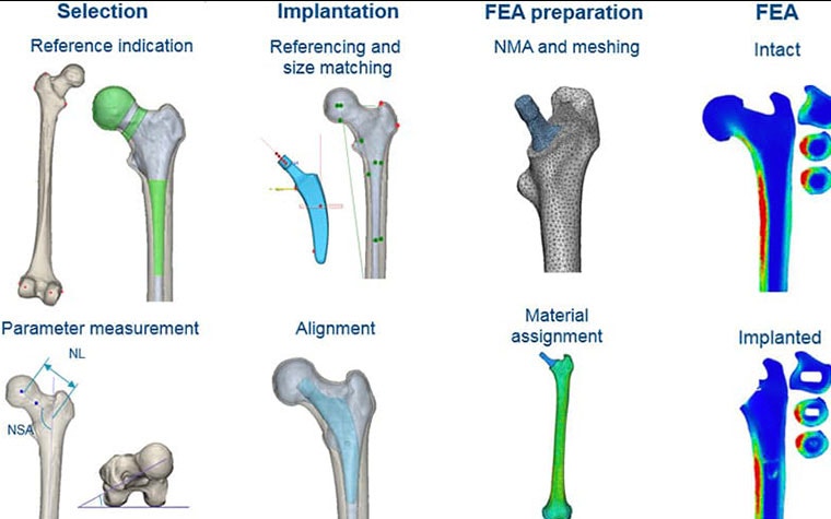
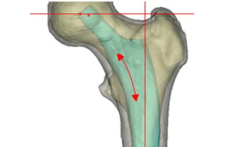
To select the femurs to be used in the study, the neck-shaft angle (NSA), neck length (NL), and anteversion (AV) were determined three-dimensionally from a CT dataset of 96 segmented femurs. The 12 most extreme and six 'average' femurs from this dataset were selected (18 femurs). Then, the CAD design files of the implant were automatically sized and aligned to restore the anatomical hip rotation center. The stem size and position were manually corrected by an orthopaedic surgeon where needed to achieve the optimal biomechanics for each femur (Figure 2).
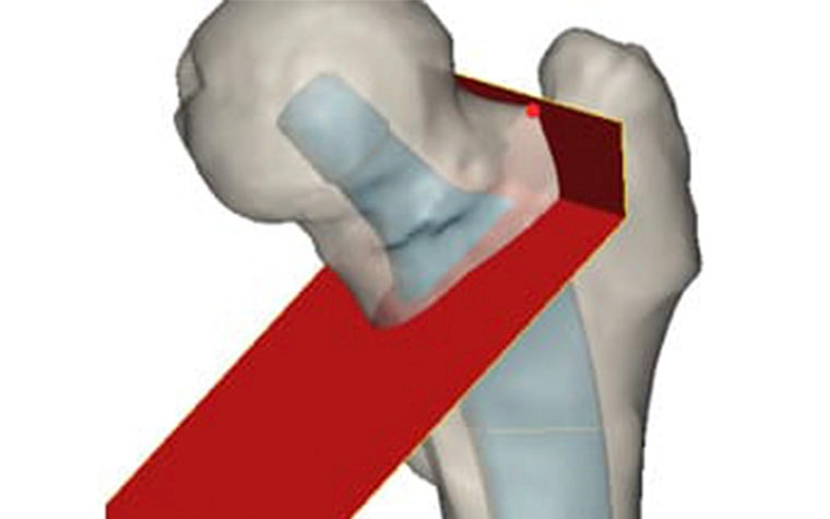
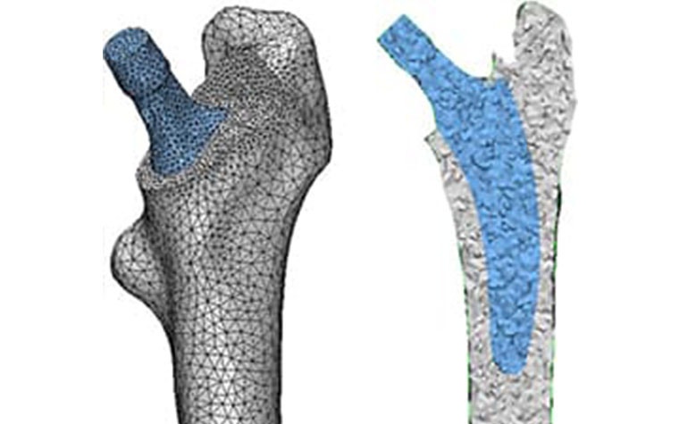
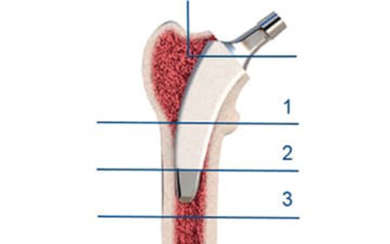
After making the virtual osteotomy cut (Figure 3), finite element models were constructed using a non-manifold assembly approach (Figure 4). Material properties were estimated from the CT dataset and loads representing walking and stair climbing were applied in Abaqus. Stress shielding was evaluated by the change in average strain energy density pre- and post-operatively in three different regions (calcar, mid stem, tip), with each being subdivided into four quarters (medial, lateral, anterior, posterior) (Figure 5).
As well as allowing the researchers to avoid repetitive tasks and devote time to more value-added tasks, automating the workflow also meant the team could study a larger study population than in previous work.
The result
A better understanding of stress shielding across a representative study population
Stress shielding was greatest in the calcar-medial zone (zone 1M in Figure 5), with a sharp reduction in strain energy density. This effect decreased towards the distal zones. Stress shielding was lowest in the 'average' femurs, while femurs with atypical geometries generally showed higher levels of stress shielding.
The neck shaft angle was the most influential parameter for the amount of stress shielding in the bone, while an abnormal anteversion angle had almost no detrimental effect on stress shielding.
Further, stress shielding was generally lower in femurs where the load transfer between implant and bone was located proximally, whereas the femurs with the highest levels of stress shielding had a particularly large stress concentration at the tip of the stem.
L-102653-01
Share on: