CASE STUDY
AM Simulation: a Guide to the Best Part Orientation and Support Configuration
One of the great advantages of additive manufacturing (AM) is the possibility of truly customizing parts. The technology is highly suited for producing implants designed for individual patients in areas of medicine such as cranio-maxillofacial (CMF) surgery, with optimal size, shape, and mechanical properties.
Industry
Healthcare
Key solutions
Materialise Magics
Simulation
The impact
Demonstrate that simulation can help with choosing the right orientation and support configuration
Simulate and compare the deformations of the finalized part-support configurations
The challenges of printing CMF implants
The process of producing CMF implants is challenging. If not heat-treated, the implants tend to suffer from a so-called “spring-back” effect in certain build configurations due to residual stresses. This spring-back effect causes significant deformations in the final design, which is a problem since it may not fit the individual patient anymore. How severe this spring-back effect will be depends on your part orientation and support configuration. However, developing a proper configuration is complex and time-consuming.
In this case study, we investigate different part-support configurations of a personalized CMF implant, and determine which configuration has the least spring-back and, therefore, is most suitable for the additive manufacturing process. We do this by simulating deformations via a well-calibrated inherent strain method* and comparing the final deformations of the parts after support removal. We performed an additional comparison with the manufactured design configurations to confirm the simulation results.
Simulating an entire platform in three minutes
As we explained in our previous simulation post, simulation is a powerful tool to minimize failed builds. It provides you with valuable feedback on how (not) to support or position critical regions. Let’s have a look at the simulation workflow.
- Obtain the CAD geometry of the part and support configurations
- Voxelize part geometries and consider support structures via boundary conditions
- Simulate the layer-by-layer build-up via the inherent strain method
- Interpolate the voxel results onto the original CAD geometry
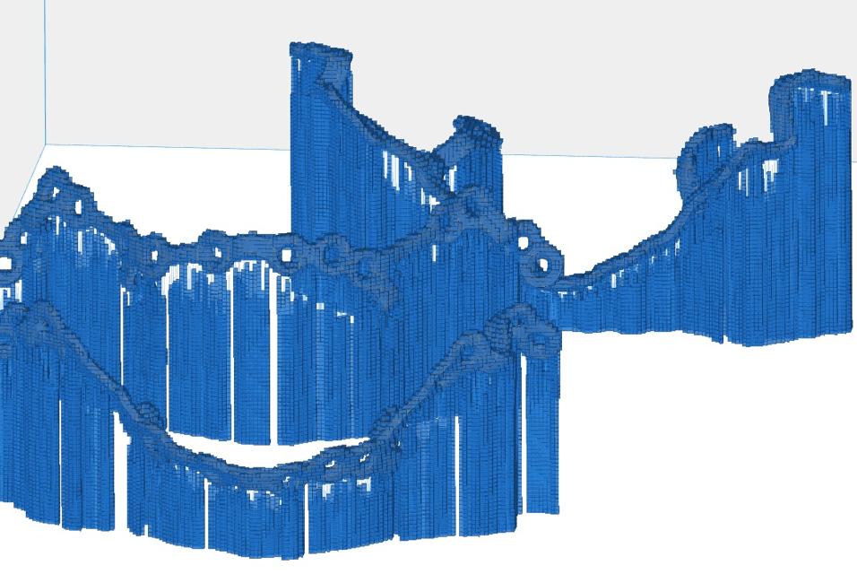
We decided to focus on simulation speed and, therefore, the voxelization of the parts is fairly coarse. Our goal here is not to simulate the exact distortion of every configuration but to determine which configuration qualitatively deforms the least. In only three minutes, we simulated the entire voxelized platform.
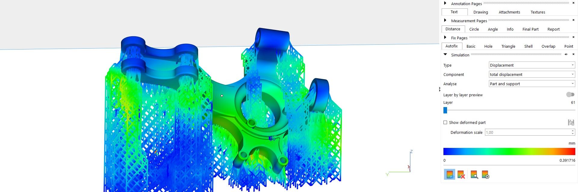
Assessing the results
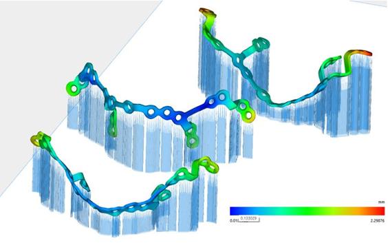
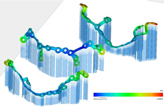
The Magics Simulation software was used to simulate and view the results. A function to selectively load the most relevant simulation data inside Magics further enhanced the workflow to find the best-fit orientation. The image below shows three different part-support configurations (transparent) and the simulated deformations of the CMF implants after removal from the support structure. As you can see, the part-support configuration with the least deformation is the configuration in the middle. This one does not contain any red or yellow zones.
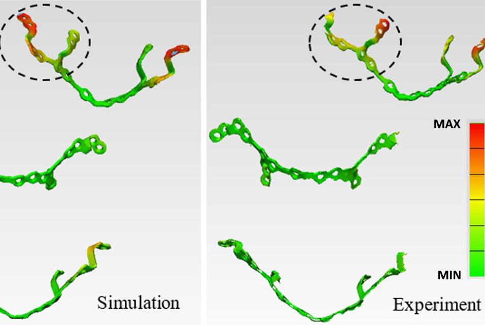
To confirm the results from the simulation, we performed a design-deviation comparison of the deformed parts with the original CAD geometry for both the simulation and printed parts. As you can see below, the simulated and the printed designs show the same deviation patterns. The top configuration has the biggest geometrical deviation from the original CAD geometry, and the middle one has the smallest deviation.
Searching for the least deformation
In this case study, we used finite element simulation to quickly predict the global deformations of three different part-support configurations of a patient-specific cranio-maxillofacial implant. The coarse voxelization approach allowed for fast simulation and quick feedback about the qualitative deformation tendencies of the configuration. Actual test prints confirmed that out of the three proposed configurations in this study, the configuration in the middle showed the least deformation after support removal.
Therefore, this second simulation case also confirms that the predictive power of simulation is a valuable tool for AM engineers. With the use of the Magics Simulation module, they can evaluate their designs prior to manufacturing, allowing them to quickly find the optimal part orientation and support configuration. Materialise leverages over 30 years of AM experience to develop AM-specific simulation approaches that will make “AM lives” easier.
*The inherent strain method (ISM) is a simulation procedure that was adapted from welding simulation to predict residual stresses and deformations during the additive manufacturing (AM) process. The ISM is a simplification of the complex, time-dependent, thermo-mechanical AM process into a simple quasi-static analysis which allows for fast and accurate simulation of complex additive components.
Please note that Materialise Magics is not a medical (device) software. The user has the responsibility to validate the production process and their product for use as a medical device. Materialise's orthognathic implants are protected by patents EP 2398411, US 8,784,456, US9,247,972, US 9,339,279. Further patents pending.
Featured products and services
Identify error-prone areas of your build before printing so you can get it right the first time, every time.
Improve production efficiency, automate repetitive tasks, and optimize print success rates with industry-leading data and build preparation software.
Share on: